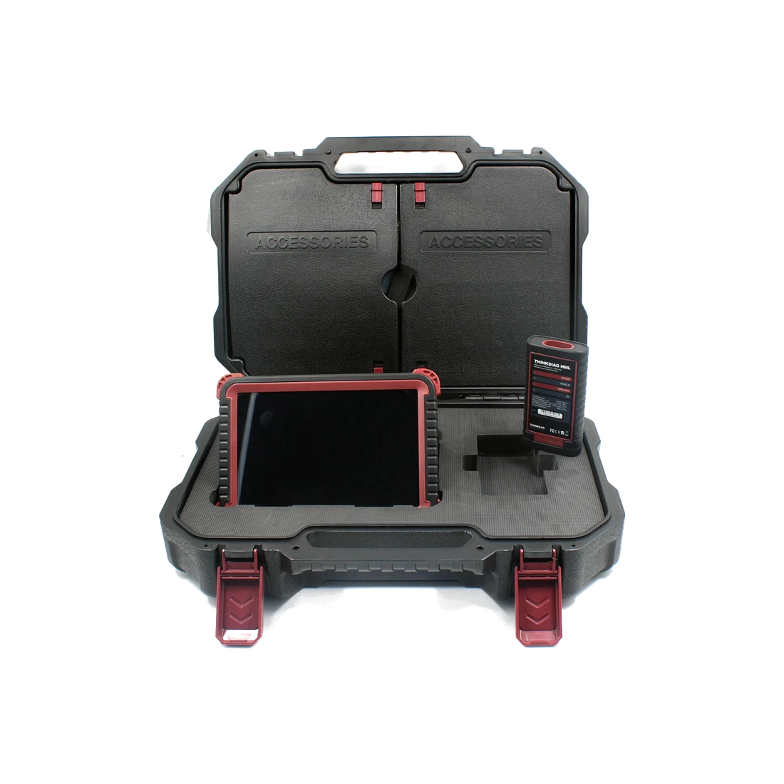
Product information
What is the Autel MS908CV II used for?
The MS908CV II is designed for professional workshops that service light commercial vehicles, trucks, tractors, or buses in the same facility. 12 V or 24 V power compatibility alone does not guarantee vehicle support.
Before purchasing, the vehicle's brand, model, model year, engine or chassis information; the target control unit, the operation to be performed, the required connector, and VCI must be verified together on Autel's current coverage screen.
Vehicle Coverage
What vehicles does the Autel MS908CV II support?
The make name alone does not guarantee compatibility. Within the same make, model year, engine, chassis, control unit, communication protocol, and intended operation can yield different support results.
- Vehicle Group
- Light, medium, or heavy commercial vehicle classes included in the product software
- Supported makes
- In heavy/medium-duty: DAF, Hino, Fuso, UD, Mercedes-Benz, Volvo, Scania, Iveco, Isuzu, Kenworth, Peterbilt, Freightliner, International, Autocar, Agrale, and Volkswagen; in light-duty: Ford, Iveco, Fiat, Renault, Peugeot, Citroën, Opel, MAN, Dodge, Toyota, Nissan, Mazda, Suzuki, and Daihatsu are seen in official documentation.
- Supported models
- Model year, engine, chassis, and desired function for Iveco Daily and Ford Transit; vehicle and ECU version for DAF are verified separately on the Autel coverage screen.
- Scope of service
- Code reading, live data, active test, service function, coding, and programming may be supported separately.
- Connection conditions
- Brand-model-year coverage, Cable and adapter set, MaxiVCI V200 requirement
- The make and model examples on the page do not guarantee all production years and all functions.
- Before any definitive operation, the manufacturer's current coverage record must be verified with the VIN or full vehicle information.
Open official sources and coverage connectionsProduct details
What diagnostic tasks does it perform?
The device performs full module scans on supported commercial vehicle control units; reads and clears fault codes, displays live data, and sends bi-directional active test commands. Expert Mode provides direct access to manufacturer-specific system components such as engine, transmission, and brakes when vehicle coverage permits.
Mandatory DPF regeneration, electronic parking brake, oil and service light resets, injector cut-off tests, and injector coding are among Autel's official function examples. The presence of these names in the device menu does not mean the same operation will be available on every vehicle.
Function support is verified separately for specific vehicles, model years, and control units.
- AutoScan on all modules
- Fault code reading and clearing
- Live data viewing and graphing
- Bi-directional active test
- DPF, EPB, oil maintenance, and injector services on supported vehicles
Product details
How to evaluate 12 V and 24 V vehicle connections?
Autel's technical datasheet specifies the tablet's input voltage as 12 V nominal, within a range of 9–24 V. Autel's support documentation also states that the MS908CV II can be used on 24 V vehicles. This information clarifies the device's electrical operating range; it does not solely indicate that the software will connect to a specific vehicle.
With the light-duty software, 12 V light commercial vehicles are within the target scope. For medium and heavy-duty software, the appropriate cable set is used for connections to 24 V trucks, tractors, and buses. Before connecting, the vehicle socket, power supply, protocol, software selection, and physical connector are matched.
- Electrical input range: 9–24 V
- Brand-model-year check on 12 V light commercial vehicles
- Appropriate connector check on 24 V medium and heavy-duty vehicles
- Voltage compatibility does not guarantee vehicle and function compatibility
Product details
Results for Iveco Daily, DAF, and Ford Transit
Iveco is listed in Autel's medium/heavy-duty menu and in the light-duty brand list. Therefore, the answer for the Daily family is not definitively determined by the model name; the model year, engine, chassis, and the intended operation are selected on the Autel scope screen.
DAF Truck software is listed in Autel's official CV update notes with engine, transmission, brake, exhaust aftertreatment, and instrument systems. Ford is also included in the light-duty brand list; for Transit, the specific model year, engine, and control unit must be verified. The latest light-duty protocols may also require the MaxiVCI V200.
- Iveco Daily: brand in scope; specific vehicle and function check required
- DAF: official DAF Truck software available; function may vary by ECU version
- Ford Transit: Ford light-duty in scope; model-year and function check required
Product details
Are the MaxiFlash and MaxiVCI V200 the same device?
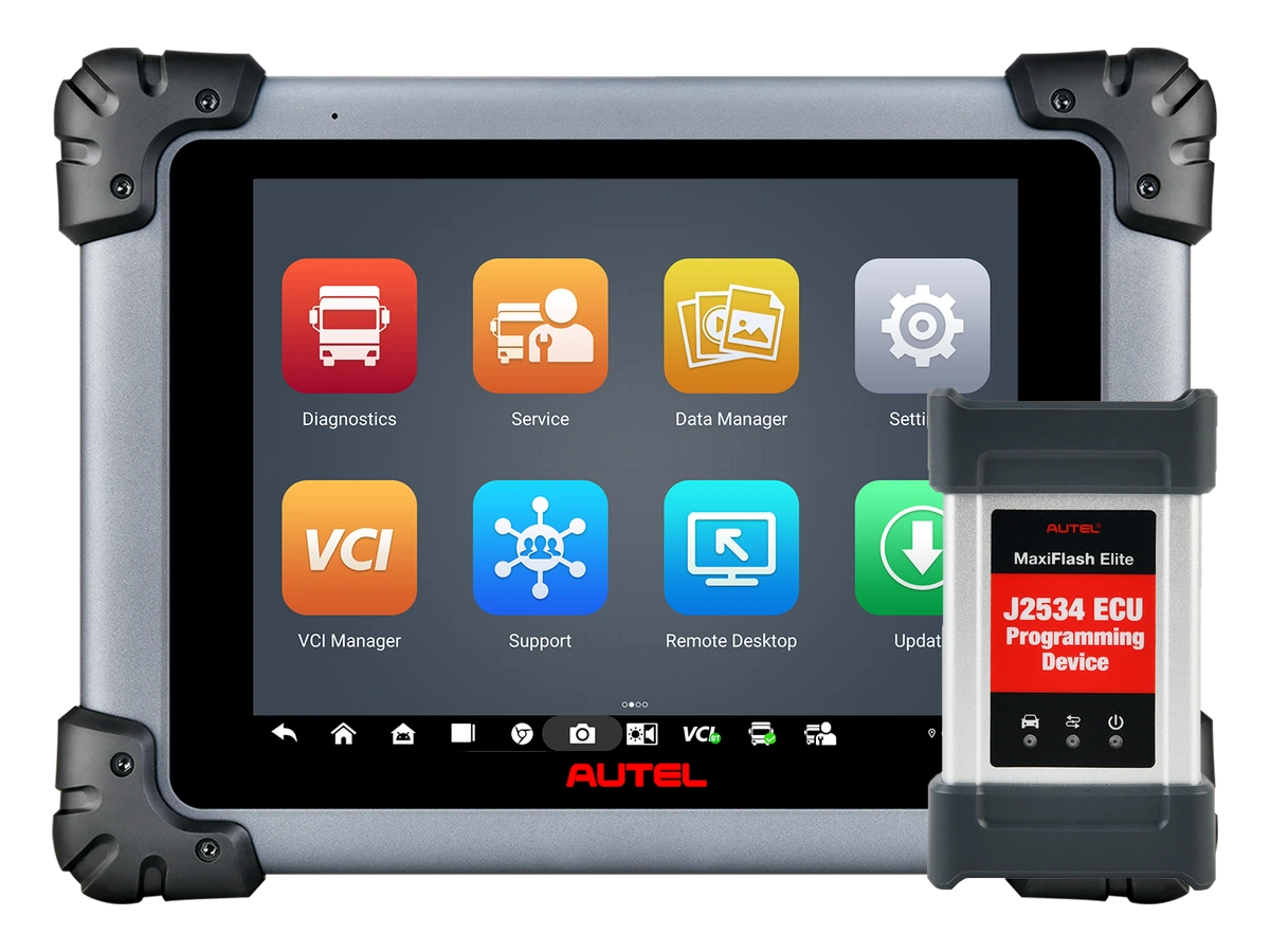
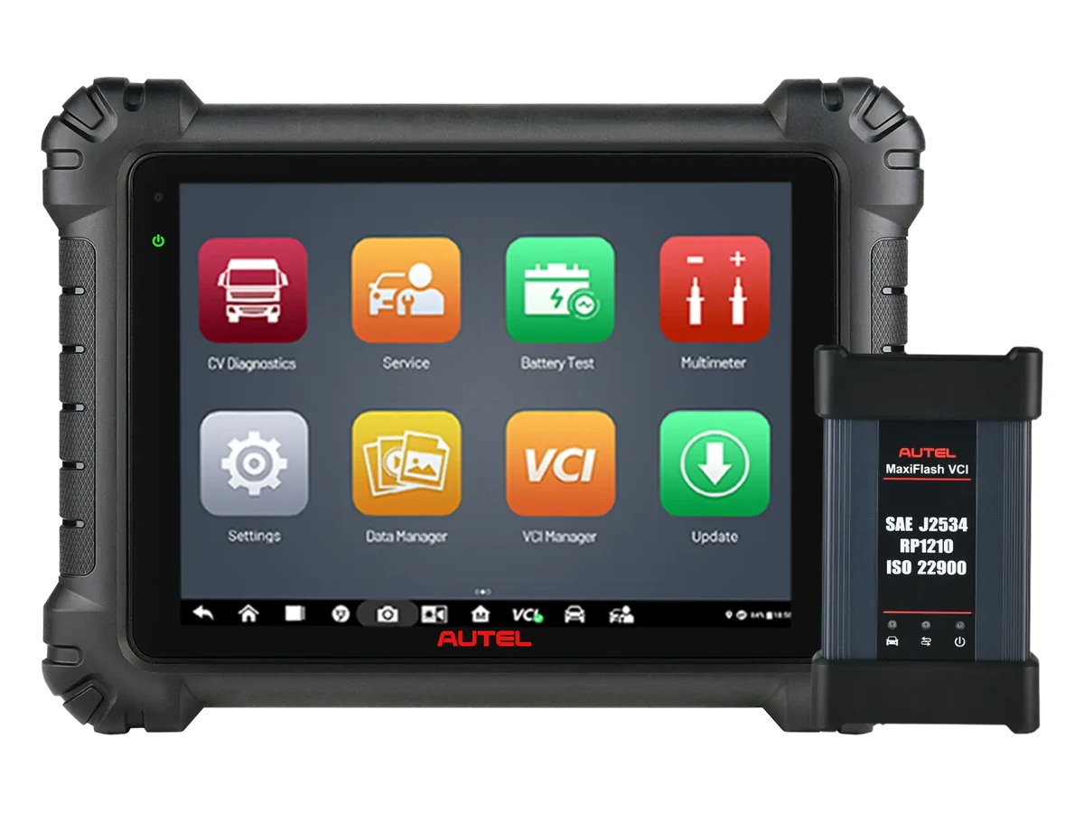
No. Autel identifies the MS908CV II with the MaxiFlash VCI for wireless Bluetooth vehicle communication and J2534 pass-thru interface. The same official product page states that the MaxiVCI V200 must be purchased separately for access to the latest communication protocols on light-duty vehicles.
Therefore, the presence of the standard MaxiFlash does not eliminate the need for the V200 on new light-duty commercial vehicles such as the Ford Transit or Iveco Daily. The exact list of tablets, VCIs, cables, and adapters to be delivered in Turkey must be checked from the sales package; a box image from another country is not considered proof of the local package.
- MaxiFlash: wireless VCI and J2534 interface
- MaxiVCI V200: separate product for latest light-duty protocols
- Connector set: selected according to vehicle socket
- Local delivery list to be confirmed before ordering
Product details
Tablet and connection technical specifications
The official technical datasheet includes Android 10 operating system, an octa-core processor consisting of a 2.2 GHz quad-core A73 and a 1.8 GHz quad-core A53, 4 GB of RAM, and 128 GB of internal storage. The 9.7-inch LED capacitive screen has a resolution of 2048 × 1536 pixels.
Connectivity is listed as Wi‑Fi 802.11 a/b/g/n/ac, USB 2.0, Bluetooth 5.0 + EDR, up to 64 GB SD card, and HDMI. The rear camera has 16 MP autofocus and flash.
An 11,000 mAh lithium-polymer battery, 6.5 W power consumption, and operating and storage ranges of 0–50 °C and −20–60 °C, respectively, are other values published by the manufacturer.
- Operating System
- Android 10
- Processor
- 2.2 GHz A73 quad-core + 1.8 GHz A53 quad-core
- Memory
- 4 GB RAM / 128 GB storage
- Screen
- 9.7-inch / 2048 × 1536
- Wireless connection
- Wi-Fi and Bluetooth 5.0 + EDR
- Other connections
- USB 2.0, HDMI, up to 64 GB SD card
- Battery
- 11,000 mAh / 3.7 V lithium-polymer
- Input voltage
- 12 V nominal / 9–24 V range
Product details
Initial scan upon vehicle acceptance
The make, model, model year, engine, and chassis information of the commercial vehicle arriving at the service department are recorded on the work order. The diagnostic socket on the vehicle is identified; the correct connector, 12/24 V power supply, and software group are selected. After turning on the tablet and VCI, the vehicle identification and communicating control units are read first.
The entire system scan is saved without clearing codes. Accessible modules such as engine, transmission, brakes, instruments, and exhaust aftertreatment appear separately in the initial report. The customer's complaint is added next to this record; a single fault code does not lead to an immediate parts replacement decision.
The VCI model, software version, connection time, and adapter used are added to the same service record.
- Vehicle identification and socket check
- Correct software and connector selection
- Full system scan without clearing codes
- Recording VCI and software version
Product details
Examining engine and emissions faults
For vehicles with an engine fault or exhaust aftertreatment warning, the current and historical codes of the relevant control unit are read together. Operating hour, temperature, pressure, RPM, and load data associated with the code are saved to the extent accessible.
The technician selects only the live data channels related to the complaint and adds the vehicle conditions at the time of measurement to the report. When evaluating DPF saturation or regeneration needs, sensor data, physical inspection, and the vehicle manufacturer's service procedure are used together.
The appearance of the forced regeneration menu does not automatically make the process safe; the command is not initiated before the preconditions are met. After the repair, the same codes and data channels are read again.
- Separating current and historical codes
- Reading live data with event data
- Applying regeneration preconditions
- Comparing the same data after repair
Product details
Performing bi-directional active tests
Before starting an active test, the correct vehicle and control unit selection is re-verified. If a fan, pump, valve, relay, or another actuator is to be moved, the work area is cleared, and mechanical risks are eliminated. Vehicle voltage and connection status are saved as the initial record.
The command given from the device is not solely based on the "successful" message on the screen; the physical response of the component, live data changes, and any sound or pressure results are observed together. If the command does not produce the expected response, the same test is not forced repeatedly. Power supply, wiring, fuses, relays, and control unit conditions are examined separately.
The test result is recorded on the service form along with the menu used and vehicle conditions.
- Safe area for moving parts
- Voltage and connection record before command
- Comparing screen response with physical reaction
- Reporting results with vehicle conditions
Product details
Final check after service procedure
When DPF regeneration, injector coding, oil maintenance, brake service, or another supported service function is completed, the device reconnects with the same vehicle record. The result shown during the procedure, the physical maintenance performed, and the replaced part are distinguished on the service form.
The control units from the initial scan are read again; cleared, returned, and ongoing codes are shown separately. If live data comparison is required, engine RPM, load, temperature, and test time are kept as consistent as possible with the initial record. Dashboard warnings and the vehicle's physical operation are also checked.
The final report explains the initial findings, the procedure performed, and the observed results together, not just the success message in the device menu.
- Keeping initial and final scans in the same vehicle record
- Separately documenting the physical operation performed
- Separating returned codes
- Checking dashboard and physical operation
Product details
What limits are observed during use?
During writing and service operations such as coding, programming, or regeneration, the vehicle manufacturer's procedure is followed; vehicle voltage is kept stable with a suitable power supply, and the VCI connection is not interrupted. During active tests, the area around fans, pumps, valves, and mechanisms that may move is kept clear.
The appearance of a menu does not solely prove that the operation is safe or supported for the vehicle. The manufacturer's scope record, the preconditions on the device screen, and the vehicle's service documentation are applied together. Connection is not established with damaged cables, connectors, or the VCI.
- Stable vehicle voltage during writing operations
- Uninterrupted tablet-VCI-vehicle connection
- Safe work area before active test
- Vehicle manufacturer's service procedure
Product details
What vehicle information should be prepared before ordering?
Simply writing "Iveco," "DAF," or "Ford" is not sufficient for compatibility checks. The complete model, production year, engine type or engine code, the part of the chassis number sufficient to identify the vehicle, a photo of the diagnostic socket, and the intended operation should be prepared.
For example, a request for code reading only will not yield the same scope result as an active test, injector coding, or regeneration on a specific control unit. If the vehicle has a non-standard socket, the required connector must also be identified. For new light-duty commercial vehicles, the need for the MaxiVCI V200 should also be inquired about due to protocol requirements.
This information reduces the risk of ordering with an incorrect cable set or missing VCI.
- Full model and production year
- Engine or chassis information
- Diagnostic socket photograph
- Desired system and procedure
- Connector check with required VCI
Product details
How to compare with MS909CV and other heavy-duty devices?
When comparing MS908CV II with MS909CV, not only the vehicle group name is considered. Tablet hardware, VCI structure, delivered connector set, current software coverage of vehicles arriving at the service, and the service operations used by the workshop are evaluated in the same list.
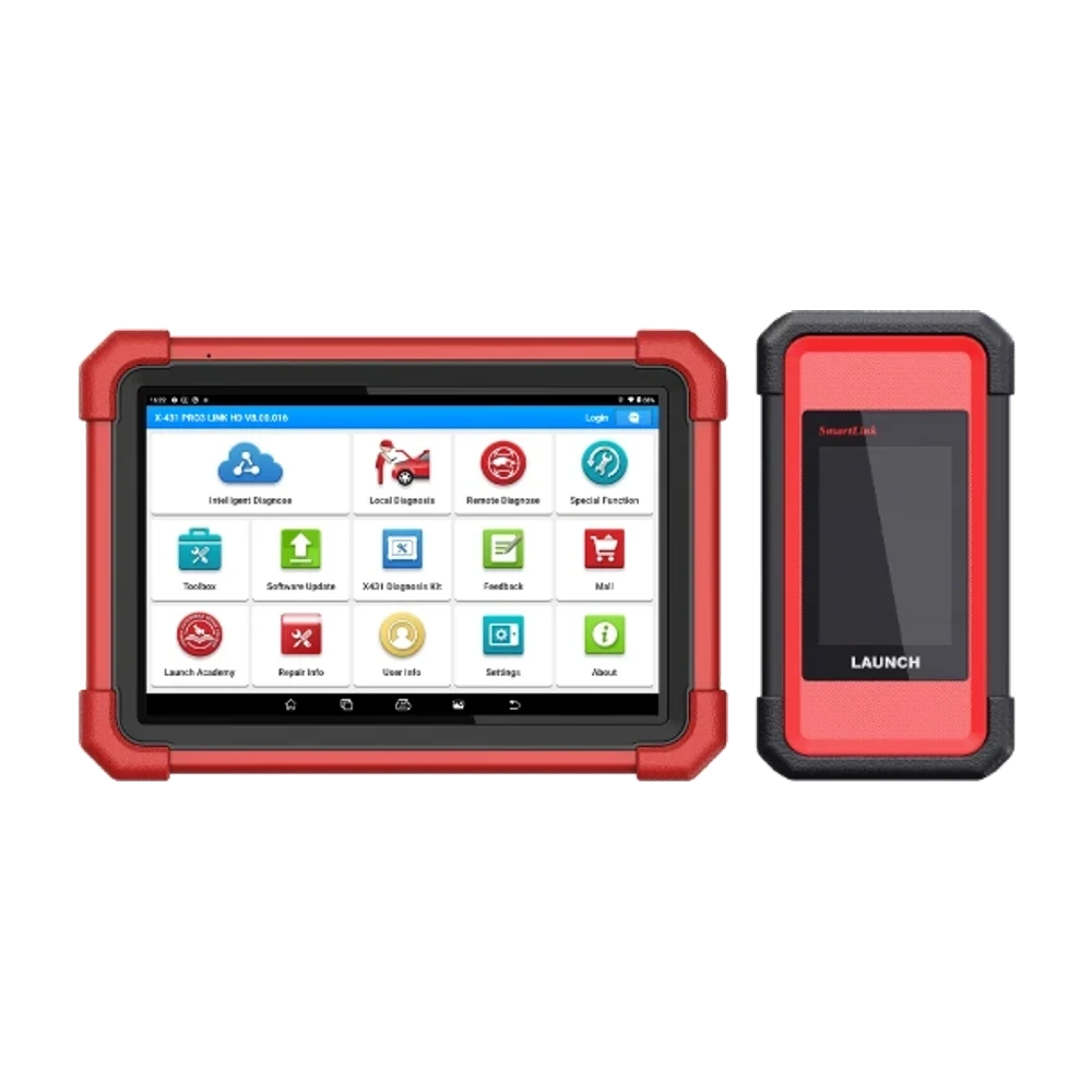
The same criteria should be used for other commercial vehicle devices such as Launch X‑431 PRO3 LINK HD or Thinktool Master CV. Price difference can be compared if the required cable, VCI, software, and vehicle coverage meet the same purchasing need.
Services that only work on passenger cars should separately evaluate passenger car-focused professional tablets instead of CV packages.