Product information
What is the THINKCAR CE EVP 802 used for?
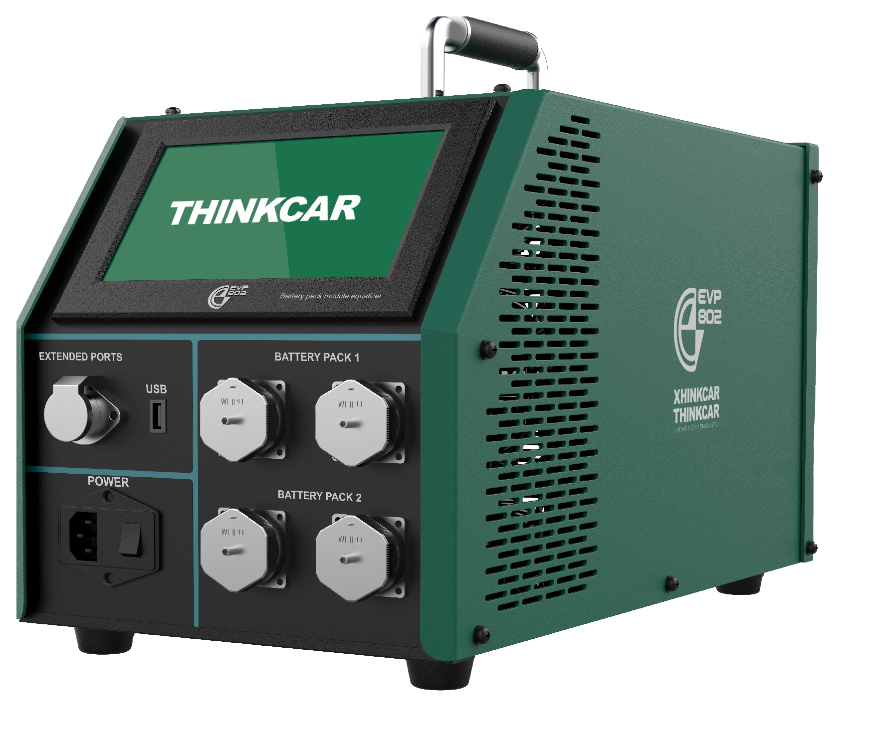
The THINKCAR CE EVP 802 is professional equipment used for cell-level charge, discharge, and balancing maintenance in compatible electric vehicle battery modules. It supports connections for up to two groups, with 12 cells per group. The cell operating voltage is specified as 1.8–4.2 V, and the charge/discharge current range is 0.1–5 A.
The total power ceiling is 600 W. These limits do not mean it can be directly connected to all electric vehicle batteries. Working with high-voltage batteries requires competent personnel and the battery manufacturer's service instructions. The CE EVP 902 module is not to be confused with charge/discharge devices or the newer EVP 803 model.
Vehicle and part coverage
In which vehicles is the THINKCAR CE EVP 802 used?
A make-model software list, as found in diagnostic devices, does not apply to this product. Compatibility is determined by the part to be measured, the electrical system, the operating range, the probe or connection method, and the manufacturer's safety limits.
- Vehicle make
- Evaluated not by brand, but by the product's technical measurement or service limit.
- Vehicle model
- Further evaluated if the system to be measured and connection condition are within the technical range.
- Technical limitation
- Up to 2 × 12 cells, 1.8–4.2 V cell range, 0.1–5 A, 7-inch display
- Diagnostic Scope
- Does not include vehicle control unit software or make-specific service menus.
- Measurement range and safe connection conditions are verified from the product's official technical documentation.
Open official sources and coverage connectionsProduct details
What problem does cell balancing address?
The voltages of cells within a module can differ. Balancing aims to bring this difference closer to the target level under suitable conditions. However, all cells showing the same voltage does not prove their capacity or internal state is the same. Physical damage, leakage, insulation issues, or significant capacity loss are not considered resolved by balancing alone.
The technician first investigates why the cell difference occurred; the device is not used as an automatic solution for every battery complaint. The test record also includes the initial state, cell chemistry, and temperature. Manufacturer marketing claims about battery performance are not converted into guaranteed range increase or lifespan extension on this page.
Product details
How is the 2 × 12 cell connection understood?
The device is defined for up to two module groups, with up to 12 cells per group. The total of 24 cells does not imply that a single 24-cell configuration can be used in all cases. The group configuration, connection terminals, and cell count are selected according to the manual.
A lower cell count does not eliminate voltage or chemistry limits. Similarly, a compatible external module size is not proof of electrical compatibility. This capacity refers to the compatible connection group that can be processed simultaneously; it is not a promise of direct access to the vehicle's entire traction battery regardless of brand.
- Module group
- Up to 2 groups
- Cells per group
- Up to 12
- Cell voltage range
- 1.8–4.2 V
- Charge/discharge current
- 0.1–5 A
- Total power ceiling
- 600 W
- Screen
- 7-inch capacitive touch
- Housing / weight
- 496 × 246 × 262 mm / 14 kg
Product details
Charge, discharge, and balancing are separate functions
The operating menu separates charge, discharge, and balancing options. The selected mode must be appropriate for the test's purpose and the cell's allowed operating conditions. Constant current and constant voltage control for charging, and constant current operation for discharging are described.
The target voltage or termination condition is not selected independently of the battery manufacturer's limits. A suitable value for one cell is not transferable to cells of a different chemistry. The presence of a battery type in the manufacturer's menu does not imply that all instances of that type are supported at all voltages.
Screen data and temperature are monitored during operation; protections do not substitute for correct settings and connections.
Product details
Service scenario: cell voltage difference in a module
When a cell difference is observed in diagnostic information from a vehicle, the operating conditions under which the measurement occurred are first examined. After completing the necessary vehicle safety procedures, the cell structure and connections of the compatible module are verified. The technician records the pre-balancing values, sets the targets according to the battery instructions, and monitors the process.
At the end of the process, not just the highest and lowest values, but the behavior of all cells is compared. If the difference reappears in the same cell, its cause is investigated further. Completion of balancing does not mean that cell's capacity is equal to others or that all vehicle battery issues are resolved.
Product details
Service scenario: post-maintenance check of a module
After supported module maintenance, the voltage status of the cells may be checked. First, it is confirmed that the maintenance performed was completed using the battery manufacturer's approved method. The device's connection configuration and cell count are matched to the module; the process is not initiated with an incorrect sequence or incompatible connector.
The balancing result is compared with the initial record, and the test conditions are saved. Reinstalling the module in the vehicle, insulation checks, and final tests on the vehicle side are separate service steps. This equipment does not replace those steps. The 'completed' message on the screen refers only to the device operation performed; it is not a certification of safe use for the entire vehicle.
Product details
Service scenario: converting maintenance data into a report
The technician assigns the correct module or work order ID to the test group. During operation, voltage, current, temperature, and status information are monitored; the mode in which the test was performed is recorded. Completed data can be reviewed graphically and tabularly, and transferred via USB. Files are distinguished by module, even if they belong to the same customer.
A report does not consist solely of a screenshot of the results screen; the initial conditions and the operation performed must also be understandable. The results explained to the customer remain within the limits of the measured data. Capacity, insulation, or road tests that were not actually performed are not presented as part of this balancing report.
Product details
Display, graphs, and data transfer
The seven-inch touchscreen is used to monitor the operating group, cell voltages, current, and operational status. The manual explains histogram, curve, and table displays for data queries. Transfer can be done via USB drive; supported computer software is used in the report generation process.
No promise of built-in wireless connection is made: the manual describes the Wi-Fi section as external. TCP/IP and USB-Device sections are also in the context of expansion functions. These connections do not imply ready compatibility with all vehicle BMS systems. File transfer and direct diagnostic communication within the vehicle are distinct operations.
Product details
Balancing and temperature connections
Balancing and temperature sampling connections for each group are located on the front panel. The manual distinguishes between 16-pin balancing and 24-pin temperature interfaces. Sockets have different functions; a physically similar cable is not the correct cable.
The cell connection order and temperature monitoring configuration are followed from the manufacturer's manual and the battery's service procedure. This page is not an application guide for opening high-voltage packs or making connections to cell terminals. Work is performed by trained personnel with appropriate insulation and protective equipment.
Testing is not started without checking for the possibility of short circuits, reverse polarity, and damaged cables.
Product details
Discharge heat and workshop layout
The manufacturer explains that energy from the battery is converted to heat in the device's load section during discharge. Therefore, airflow, fan area, and surrounding materials are important. The operating area must be free of conductive dust, corrosive, or explosive gases. The manual specifies an operating temperature range of −5 to 40 °C.
The surface on which the fourteen-kilogram device will be placed and the method of transport are selected accordingly. The mains input, grounding, and installation suitability are assessed by qualified personnel. The nominal 220 V connection configuration in the manual is the basis; protective functions are not a safeguard that compensates for faulty installation. Ventilation openings are not blocked during operation.
Product details
What connections are included in the manufacturer's package?
The standard list in the manufacturer's user manual includes the main device, AC220-10A power cable, two balancing main cable sets, two balancing clip leads, a USB drive, product documentation, and a quick start guide. This list does not imply that all vehicle-specific connectors are included. The module's connection method must also be compatible.
Battery lifting equipment, insulation testers, diagnostic tablets, and personal protective equipment are not substitutes for this device, nor are they automatically included in the package. The physical condition of cables and connection terminals is inspected upon delivery. Missing or incompatible connection parts are not improvised.
Product details
Cell balancer or module charge/discharge device?
The 802 model is selected for managing voltage differences between cells in a compatible module. The 902 model is for controlled charge/discharge and capacity testing of compatible modules in the DC 2–260 V range. The two products do not answer the same question with the same method.
Equipment selection changes depending on whether the service need is to equalize cells, measure module capacity behavior, or diagnose BMS faults in the vehicle. A diagnostic tablet also does not perform physical balancing.
When setting up a workshop, different tasks and safe working infrastructure are planned together; the presence of other functions is not assumed solely based on a higher device number.