Product information
What is the THINKCAR CE EVP 902 used for?
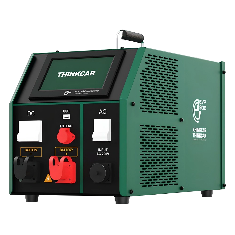
The THINKCAR CE EVP 902 is professional equipment used for controlled charge/discharge in compatible lithium battery packs and modules during electric vehicle battery maintenance. It operates in the DC 2–260 V range.
Separate upper limits of 100 A and 4.4 kW on the charging side, and 150 A and 7.2 kW on the discharge side apply; the highest current cannot be used at all voltages. The device is not a household EV charger, a 12 V jump starter, or a universal system that directly tests the entire traction battery.
Usage requires personnel competent in working with high-voltage vehicles and the relevant battery manufacturer's service procedures. Features of the CE EVP 903 model are not transferable to this product.
Vehicle and part coverage
In which vehicles is the THINKCAR CE EVP 902 used?
A make-model software list, as found in diagnostic devices, does not apply to this product. Compatibility is determined by the part to be measured, the electrical system, the operating range, the probe or connection method, and the manufacturer's safety limits.
- Vehicle make
- Evaluated not by brand, but by the product's technical measurement or service limit.
- Vehicle model
- Further evaluated if the system to be measured and connection condition are within the technical range.
- Technical limitation
- DC 2–260 V, 4.4 kW charge ceiling, 7.2 kW discharge ceiling, 7-inch touchscreen
- Diagnostic Scope
- Does not include vehicle control unit software or make-specific service menus.
- Measurement range and safe connection conditions are verified from the product's official technical documentation.
Open official sources and coverage connectionsProduct details
What does charge and discharge testing of a battery module indicate?
Reading a battery module's voltage at a single moment does not solely explain how much energy it can deliver under load. Controlled charge and discharge help monitor the module's behavior under defined start and end conditions. The test record also includes voltage, current, duration, and temperature conditions.
If different currents, temperatures, or end thresholds are applied to the same module, the results are not directly considered equivalent. The test device performs this operation; it does not automatically create the vehicle manufacturer's module acceptance criteria. The purpose of the measurement may be maintenance, capacity analysis, or specific service preparation.
Specifying the problem being investigated in the work order is more useful than just transferring the final screen numbers to the report.
Product details
Read charge/discharge voltage and power ceilings together
Three separate limits are present in the technical table. The DC 2–260 V operating range describes the voltage limit of the compatible module that can be connected. 100 A for charging and 150 A for discharging are the current ceilings. Along with these, power limits of 4.4 kW and 7.2 kW apply respectively.
For example, multiplying 260 V by 100 A does not mean the device provides 26 kW of charging; such usage is outside the power limit. The operating settings must be compatible with the battery's allowed values and all of the device's limits. If the full pack voltage is not compatible, connection is not made solely based on the assumption that the vehicle brand is supported.
- Charge / discharge voltage
- DC 2–260 V
- Charge current
- Up to 100 AValid with a 4.4 kW power ceiling.
- Discharge current
- Up to 150 AValid with a 7.2 kW power ceiling.
- Screen
- 7-inch touchscreen, 800 × 480
- Internal storage
- 16 GB
- Housing / weight
- 512 × 295 × 339 mm / 28 kg
Product details
Constant current, constant voltage, and constant power
The manufacturer defines charge control with a constant current and then constant voltage approach. For discharge, constant current and constant power operating modes are available. These options serve different test purposes; they are not equivalent buttons to be randomly selected on the same module.
In constant current, the set current target is important, while in constant power, the required current behavior depending on voltage change is important. The device's limits and the battery manufacturer's instructions are valid in both cases. The test's termination condition is determined beforehand.
If the operating mode and termination thresholds used for comparing capacity results are not recorded, it becomes difficult to understand why different tests yield different results.
Product details
Service scenario: module with capacity complaint
For a vehicle with range or capacity complaints, diagnostic data from the vehicle is first obtained, and the module to be investigated is identified. Removal from the vehicle, de-energizing, and preparation of the work area are performed according to the vehicle manufacturer's authorized service procedure. The compatible module is examined for voltage range and test connections.
The technician monitors the charge/discharge process under the defined conditions and saves the records. The obtained result is interpreted based on the same chemistry, initial state, and test conditions. A single result does not prove that the entire battery pack is healthy or that the vehicle will provide a certain mileage range.
Insulation, physical damage, and BMS issues are investigated separately.
Product details
Service scenario: controlled energy level before maintenance
Some module maintenance operations require working at a defined charge state. The technician learns which limits apply to which module from the battery procedure; they select the appropriate charge or discharge operating mode on the device screen. Testing is not initiated without checking the cables, temperature monitoring, and connection configuration.
The voltage approaching the target on the screen does not mean all safety checks for the operation are complete. If unexpected temperature changes or connection issues are observed, the work is stopped, and the fault is investigated. At the end of the test, the module's status, the method applied, and the result are recorded in the work order.
Changing the energy level with this device does not grant permission to touch a live module with bare hands.
Product details
Service scenario: comparing two test results
When comparing pre- and post-maintenance measurements, capacity figures alone are not written side-by-side. The same module ID, test mode, current or power target, end voltage, and ambient conditions are recorded.
The difference between a module tested at a different temperature in the first run and the module in the second run is not directly considered repair success. Test data exported via USB helps preserve the trace of this comparison. Files are matched with the vehicle and work order; records belonging to the wrong module are not used.
The results report describes the test actually performed. Operating the device does not replace a road test that was not done or a safety check not completed on the vehicle.
Product details
Data records, USB, and communication interfaces
The device's internal memory is used to store test data; the manufacturer describes data transfer via USB and report generation with the relevant software on a computer. The service record keeps track of which battery the transferred file belongs to, the test date, and the operating conditions.
CAN and RS485 communication interfaces do not imply automatic access to all vehicle BMS units or that all protocols are ready. The manual addresses these connections in the context of expansion and development. Reading vehicle fault codes, ECU programming, or online manufacturer accounts are not to be confused with this equipment's primary charge/discharge function.
Software and connection requirements are determined based on the specific needs of the test to be performed.
Product details
Workshop electrical installation and cooling area
The user manual describes a single-phase, three-wire 220 V AC supply configuration. Installation and protective devices to support high charging power must be assessed by qualified electrical personnel. A power extension cord fitting into the socket is not proof that it can handle the required load.
Due to the heat generated during discharge, fan inlets and air outlets are kept open; flammable materials are not stored nearby. The manufacturer specifies an operating temperature range of −5 to 40 °C. The device's 28 kg weight must be considered in the placement and transport plan.
Testing is not started if the housing, cables, or connections are damaged; protective functions are not used as a substitute for proper installation.
Product details
Manufacturer's standard package list
The standard package list in the manual includes the main unit, AC power cables, red and black discharge cables, temperature and voltage acquisition connections, communication cables, a USB drive, and user documentation. These belong to the test configuration described by the manufacturer.
Vehicle battery lifting equipment, insulation testers, personal protective equipment, diagnostic tablets, and vehicle-specific connectors are not automatically included in this list. Upon delivery, the physical condition of cables and connection terminals is inspected. Missing or incompatible cable parts are not improvised.
Purchasing this product does not grant high-voltage work competency or access to vehicle manufacturer service information.
Product details
Selection between the 802 cell balancer and the 902 charge/discharge device
The CE EVP 802 focuses on balancing cell-level voltages in compatible modules. The CE EVP 902 is selected for controlled charge/discharge and capacity analysis of compatible modules in the DC 2–260 V range. Their presence in the same series does not make the two devices interchangeable.
Addressing differences between cells versus measuring module capacity behavior are different service questions. When budgeting for a workshop, it is first determined which problem will be solved and which existing equipment it complements. Reading error logs with a vehicle diagnostic tablet also does not replace these two physical operations.
The necessary equipment budget includes safe working space and connection accessories.