Product information
What does the Autocom CDP+ Compatible OBD2 Main Cable do?
This product is a physical replacement main cable for a compatible VCI in the Autocom CDP+ / CLASSIC format. It is not offered as an original Autocom product due to the lack of a verifiable Autocom part code or authenticity mark on the product.
Physical Connection Coverage
Which vehicles and devices is the Autocom CDP+ Compatible OBD2 Main Cable used with?
Connecting the cable, adapter, or communication module to the vehicle does not prove that the vehicle is supported by the software. The physical connector, pin layout, main device, and vehicle software must be compatible simultaneously.
- Brand coverage
- There is no fixed brand list specific to the cable; the compatible main device and vehicle socket are used as a basis.
- Model Coverage
- Vehicle model and model year are verified separately in the main device's current coverage list.
- Main unit
- VCI, tablet, or diagnostic interface specified in the product name and technical resources
- Physical check
- Connector and screw structure on the device side, 16-pin OBD2 end, Pin arrangement, Manufacturer and hardware ID of the device
- This product does not add new software, licenses, or service functions to the main device.
- Do not force connection without verifying the pin structure.
Open official sources and coverage connectionsProduct details
Verified physical structure of the cable
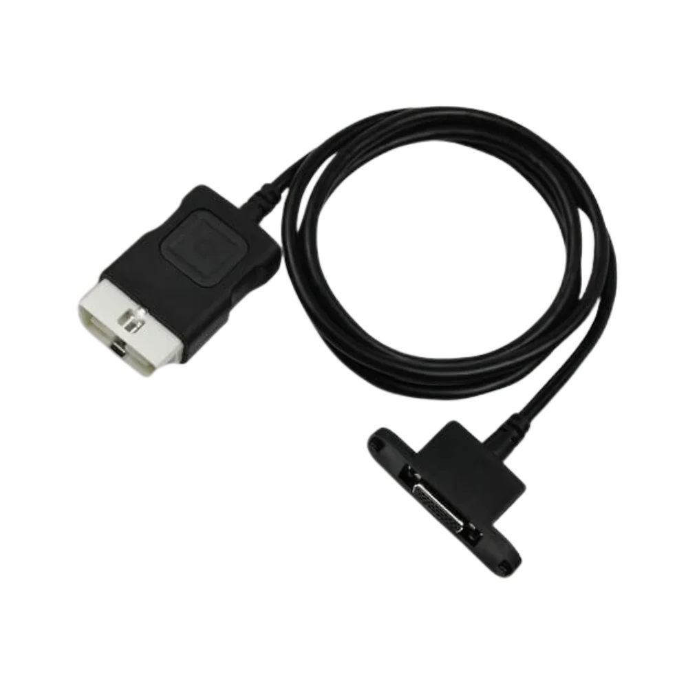
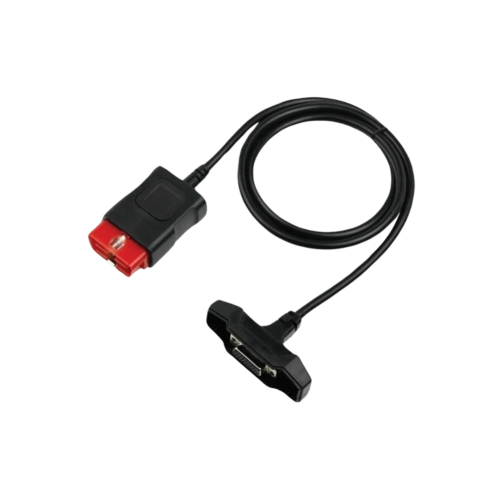
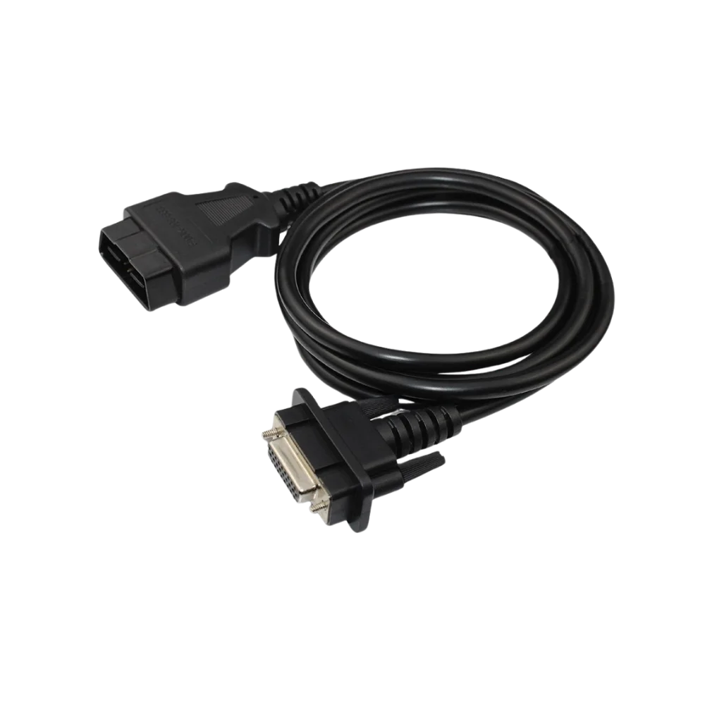
Source photos show a black cable body, a 16-pin OBD2 end with a white body on the vehicle side, and a multi-pin connector with two fixing screws on the device side. The photo does not verify the internal conductor diagram or manufacturer part code.
- 16-pin OBD2 vehicle connector
- VCI connector with fixing screws
- Black single-piece cable
Product details
How to check CDP+ compatibility?
The name Autocom alone is not sufficient. Connector placement may vary in original and compatible/copy CDP+ casings. The external shape of the socket on the device side, screw spacing, and pin arrangement should be matched with photos before delivery.
- Measure the cable entry on the CDP+ casing
- Compare D-sub screw distance with the existing cable
- Limit the initial connection to a read-only test
Product details
Package contents
The package consists of only one physical main cable. The diagnostic interface, computer, USB cable, Bluetooth hardware, Autocom CARS/TRUCKS software, and license are not included in this sale.
Product details
Photo comparison and maintenance before ordering
For ordering, clear photos showing the cable entry of the device from the front and side should be prepared. In particular, the screw spacing, corner shape of the metal plug, and the orientation of the white OBD2 end should be compared. When the product is delivered, keep the pins dry and clean; do not apply contact spray, oil, or metal tools directly into the socket.
The cable is not removed by pulling from the connector and should not be pinched between the car seat or door. If it will not be used for a long time, store it loosely coiled to protect the ends from dust. These checks increase the physical lifespan but do not change the software scope or license status of the device.
Product details
Scenario: Replacing a damaged Autocom main cable
If the CDP+ type interface in the workshop sometimes communicates with the vehicle, and the connection is lost when the cable is moved, first visually inspect both ends of the old cable and the device socket. If there is a bent pin, loose screw, or broken strain relief, compare the new cable side-by-side without removing the old part.
The white OBD2 body on the vehicle side, the metal plug on the device side, the screw spacing, and the keyway orientation should be the same. After matching, with the ignition on, perform a low-risk read first, such as only vehicle identification or control unit list.
If communication is unstable, do not proceed to programming or coding operations; check the device, software, USB/Bluetooth connection, and vehicle power supply separately.
Product details
Scenario: Initial safe connection with a replacement cable
When the cable is purchased as a spare part, do not start intensive operations immediately. First, with the ignition off, check the OBD2 end for cracks, foreign matter, and pins that have receded; then, seat the VCI side plug straight and tighten the screws evenly by hand only.
After turning on the ignition, monitor the VCI's power indicator and whether the software recognizes the device. If the same communication error occurs on multiple vehicles, the cable is more likely to be the issue; if the problem occurs on only one vehicle, check the vehicle socket, fuse, and relevant protocol separately.
This distinction prevents unnecessary parts replacement and avoids risky writing operations due to connection loss.
Technical Resources
Technical resources for Autocom CDP+ Compatible OBD2 Main Cable
Technical information verified with official sources on October 12, 2026.