Decision guide
What information should be recorded when the box is opened?
The initial registration begins with the tablet's full model name, serial number, DBScar VII VCI information, and delivered physical parts. The official manual shows the package contents as the screen tablet, VCI connector, and diagnostic cable; it also states that other accessories may vary by sales region. Therefore, compare delivered parts by name and quantity with the order and box list rather than guessing from the manual's visual. If a password envelope or activation information was delivered, store it securely with the device account. Having the serial number and account information in the same work order prevents processing with the wrong device for future software and support operations.
The main tablet, VCI, OBD diagnostic cable, charging equipment, and documents are recorded individually. The carrying case, additional adapters, or special cables are considered included in the package only if listed in the delivery list. This check is based on the actual delivery, without confusing visuals of different regional packages.
The model name on the device body and the device matching in the application must be the same. Although CRP919E BT and CRP919X BT are described in the same official product family, the model code, region, and package information are read from the purchased device. Registration attempts with a serial number or activation code belonging to another model are not made.
- Model and serial number
- DBScar VII VCI
- Cable and power parts
- Activation document
- Delivery list
Decision guide
Initial charging, account registration, and software preparation
The Launch manual requires using the power adapter supplied with the device for the initial charge. After the tablet is powered on, a Wi-Fi connection is established, and a new user account is created; users with an existing account log in directly. The registration flow in the manual uses the product serial number and the activation code from the password envelope, followed by opening the update center. During the update, the tablet's charge, network connection, and free storage space are maintained at a level that will not be interrupted. Coding or active tests on the vehicle are not attempted before the initial software preparation is complete.
If the device has not been used for a long time, a completely depleted battery may not turn on the tablet in the initial minutes; the manual suggests charging it for a short period before trying to turn it on again. Even if a different power adapter's voltage and current values appear suitable, the supplied adapter is preferred due to official warnings.
Tablet and VCI software are checked on the same delivery date. The version, date, and account information from the update screen are added to the service record. This record facilitates distinguishing between hardware, VCI software, and vehicle package in case of future vehicle connection issues.
- Charging with the supplied adapter
- Wi-Fi connection
- Account and device registration
- Updating existing software
Decision guide
Initial connection to the vehicle with DBScar VII
Before vehicle connection, the ignition position, battery voltage, and physical condition of the diagnostic socket are checked. The CRP919E BT manual requires the ignition to be on, the throttle closed, and the vehicle battery to be within the 11-14V range during the preparation phase. The DBScar VII is connected to the vehicle's OBD socket via the diagnostic cable; the VCI connection indicator on the tablet turns green when communication is established. The initial attempt should be to read the vehicle identification and scan supported systems, rather than sending a write command to the vehicle. If communication is not established, the ignition, DLC power, cable seating, VCI indicators, and Bluetooth status are checked sequentially.
The OBD socket is usually located on the driver's side, around the lower part of the dashboard; for specific placements, the vehicle service manual is consulted. Forcing the cable, connecting it at an angle, or leaving the VCI body under stress in the footwell area to access the socket can lead to connection problems and physical damage.
The ignition, gear, parking brake, or voltage conditions specified by the vehicle manufacturer may be more detailed than the general preparation in the Launch manual. Whether manufacturer procedures and stable external power support are required for write, adaptation, or coding operations should also be checked separately.
- Ignition and battery voltage
- Physical check of the DLC socket
- VCI connection indicator
- Reading and scanning as the first operation
Decision guide
How to use the health report at vehicle intake?
The Health Report function scans accessible electronic control units on supported vehicles and lists the found fault codes by system. When this scan is recorded as a "Pre-Repair" report at service intake, the electronic status of the vehicle upon arrival is preserved. The report should accurately include vehicle ID, mileage, complaint, and scan date; systems appearing only in red should not be overlooked. The manual clearly states that the DTC definition alone is not grounds for part replacement. Before proceeding, the code status, event data, live data, cable, and mechanical checks are verified.
Upon completion of repairs, a second scan on the same vehicle is recorded as a "Post-Repair" report. Comparing the previous and subsequent reports with the same vehicle ID reveals deleted, remaining, or newly generated codes. If the reports were taken under different ignition or battery conditions, this difference should be noted in the service entry.
Not every code can be erased. If there are intermittent faults, low voltage, or communication records, the time, status, and relevant data are saved first. After the code is cleared, the vehicle manufacturer's driving or re-check procedure is applied, and the system is rescanned.
- Pre-repair report
- Vehicle ID and mileage
- Code status and event data
- Post-repair report
Decision guide
View live data as a list, graph, and recording
Instead of opening all parameters simultaneously on the live data screen, values related to the complaint are selected. The manual explains the list view, single graph, and combined graph views on the CRP919E BT; combining helps to see the changes of related values on the same timeline. When investigating an idling issue, relevant values such as engine speed, air mass, fuel trim, and temperature can be selected; the exact list varies by vehicle and complaint. The unit of measurement, vehicle temperature, and operating conditions should be recorded. The reference information indicated by color on the device is not used in place of the vehicle manufacturer's technical data.
The recording function saves selected data for later playback. The technician maintains a safe operating condition instead of constantly watching the screen during testing; the diagnostic tablet is not operated by the driver if the vehicle is to be moved. The manual also states that a second person's assistance is a mandatory safety warning for tests requiring driving.
If pre- and post-repair recordings are taken under the same temperature, RPM, and load conditions, the two recordings can be compared effectively. Even if a single sensor value appears normal, the associated command, expected value, and feedback may behave differently on the same graph.
- Select relevant PIDs
- Record measurement condition
- Use graph view
- Take a second recording under the same condition
Decision guide
Safe operating sequence during active test
Active test sends a command from the device to a supported control unit, allowing observation of the part's or system's response. The tests shown in the menu vary according to the vehicle manufacturer, model year, and control unit software. Before testing, people and equipment around moving parts such as fans, valves, engines, relays, or mechanisms should be cleared. When the command on the screen is executed, the physical response, live data change, and ECU feedback are monitored together. The "Completed" message indicates that the command was executed; it does not solely prove that the mechanical part is sound under all conditions.
For example, when a fan command is given, the relay sound, fan movement, power supply, and related live data are observed separately. If the part does not operate despite the command, check the power, ground, wiring, and mechanical load. If the command is rejected by the ECU, examine the vehicle conditions, recorded faults, and test prerequisites.
If active test is applied to a system that could cause the vehicle to move unexpectedly, the manufacturer's safety procedures must be followed. Prerequisites such as parking brake, gear position, door, or hood status vary from vehicle to vehicle; a generic Launch menu does not replace these conditions.
- Secure the area of movement
- Check test prerequisites
- Monitor command and physical response together
- Record result in work order
Decision guide
ECU coding, CAN FD, and DoIP limitations
Launch lists ECU coding, CAN FD, expandable DoIP, and FCA AutoAuth features for the CRP919E BT family. The term ECU coding does not imply the ability to load new software onto every control unit; the available function depends on the brand, model, year, module, and installed software. CAN FD support is used for access to next-generation CAN networks. Vehicles requiring DoIP must have the appropriate connection equipment alongside the device and support on the vehicle side. For vehicles with a security gateway, the account, region, and manufacturer authorization affect the initiation of the process.
Before coding or adaptation, current values and control unit identification are recorded. Vehicle voltage, network connection, and device charge must remain stable throughout the process. If the intended operation is not listed in the official vehicle and function list, finding the menu on another vehicle does not constitute proof of support for that vehicle.
As DoIP is listed as "expandable," the necessary equipment is checked independently of the package. Merely having DoIP in the product name does not mean connection can be established in every vehicle without additional cables. The protocol needs of vehicles arriving at the service are examined based on brand, model, and year before purchase.
- Record ECU and operation name
- Voltage and connection stability
- Required DoIP equipment
- Security gateway account
Decision guide
Choosing between CRP919E BT, DS600, and MX808S
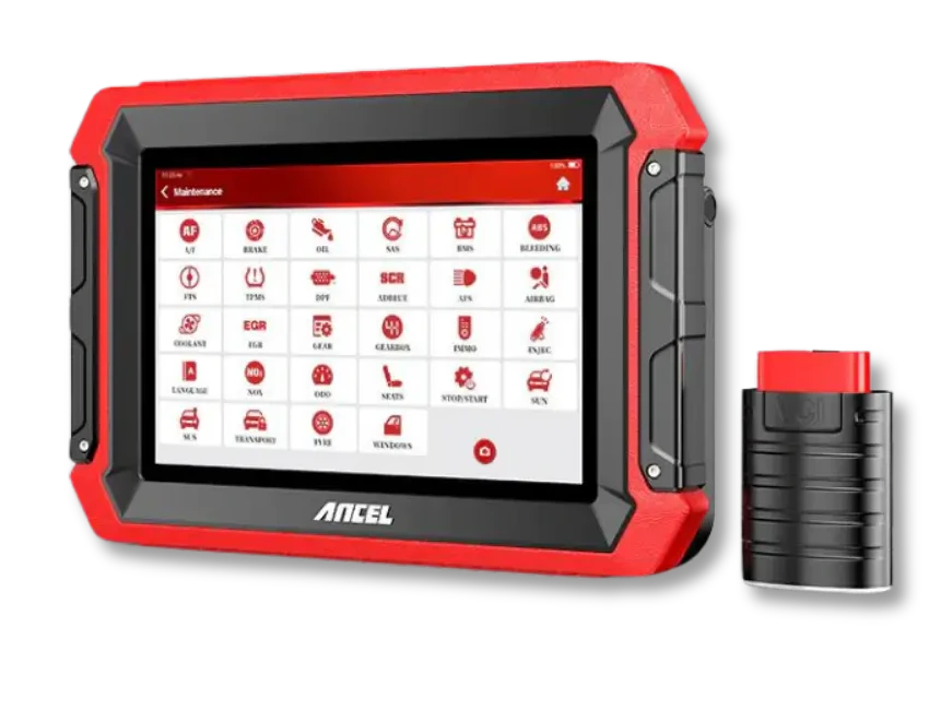
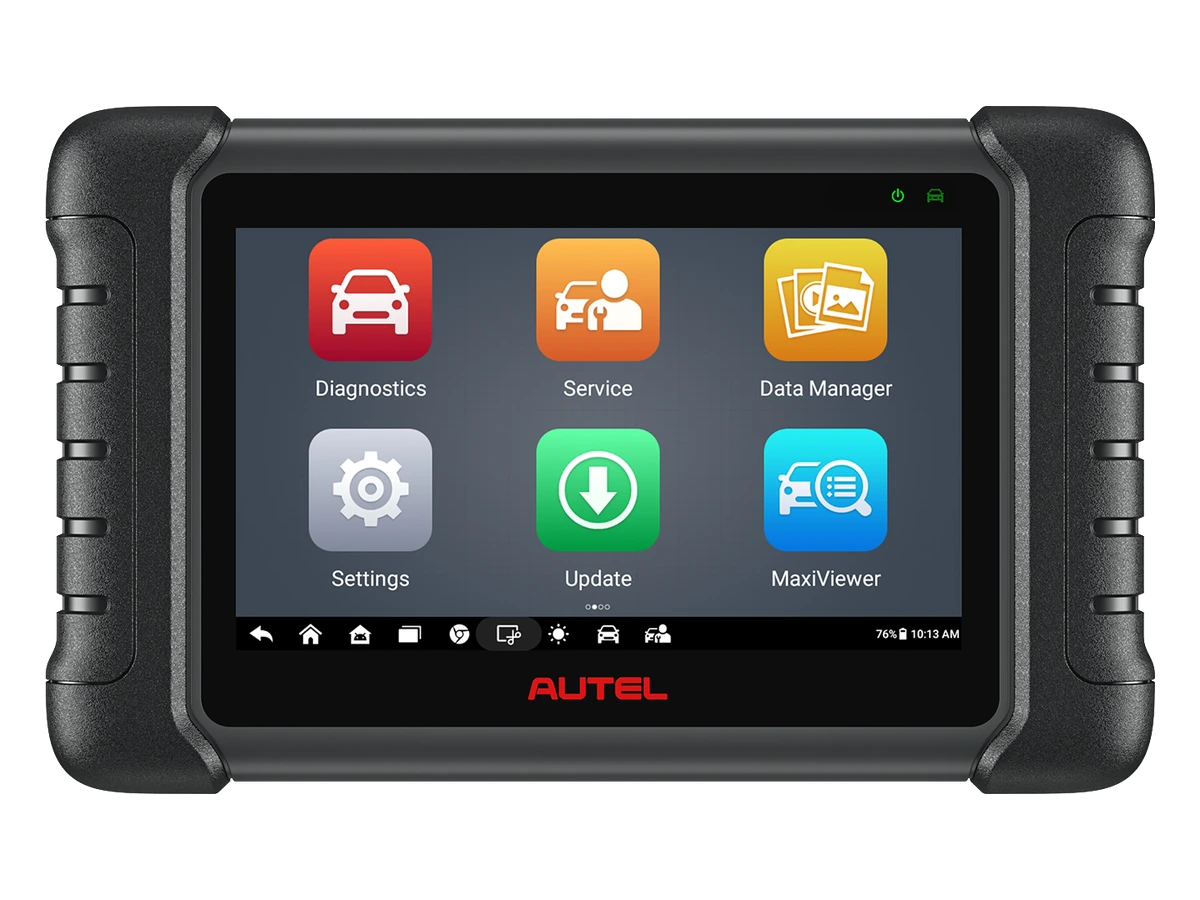
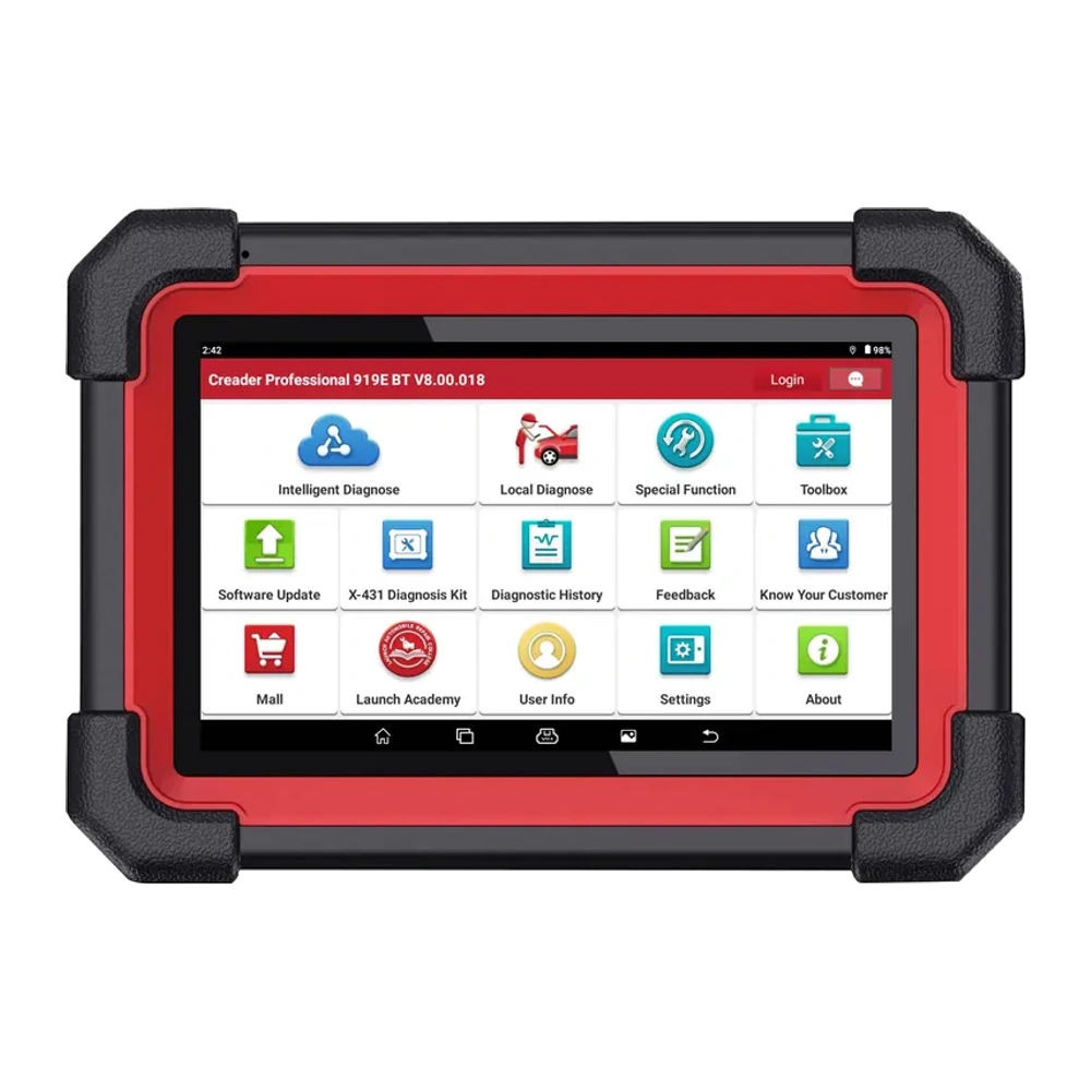
The CRP919E BT is a model reviewed by users who want CAN FD and expandable DoIP features on the same service tablet with a wireless DBScar VII connection. The Ancel DS600 caters to a different workshop setup with its wired connection and extensive physical adapter package. The Autel MX808S is compared via the Autel software flow and wired OBD connection. Ranking the three devices solely by screen price or number of service functions is not appropriate. Vehicles arriving at the service are compared using common criteria such as the protocol to be used, the need for wireless mobility, package contents, and update conditions.
If scanning and live data are used while moving around the vehicle during the day, a Bluetooth VCI is a practical distinction. If older type brand adapters or different physical connections are used extensively, the supplied cable set may be more decisive. For next-generation vehicles, CAN FD and DoIP needs are sought on a model and package basis.
A detailed comparison of DS600, MX808S, and CRP919E BT is available in a separate guide with official product resources. This user guide does not establish a purchase order; it explains how to perform the initial setup and daily registration discipline when the CRP919E BT is selected.
- CRP919E BT: Bluetooth DBScar VII
- DS600: wired connection and adapter package
- MX808S: Autel software flow
- Common criteria: vehicle and operation scope

 Launch CRP919E BT