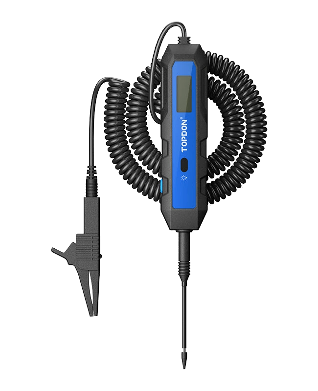
The TOPDON CT100 is a digital automotive test pen that indicates voltage and polarity in fuses, sockets, and supply lines. It helps investigate weak connections with load testing. It does not read OBD fault codes; it is not for use on high-voltage electric vehicle batteries.
What would you buy this for?
Auto electricians checking fuse and socket power
Workshops investigating voltage drops caused by wiring and connections
Users requiring a digital voltage display in 12 V and 24 V vehicle wiring
Measurement and maintenance features
3.3–65 V DC voltage and polarity check
1.2 A load test within 5–30 V range
Approx. 3.8 m cable and replaceable probe
Vehicle and part coverage
What vehicles is the TOPDON CT100 used on?
A make-model software list, as found in diagnostic devices, does not apply to this product. Compatibility is determined by the part to be measured, the electrical system, the operating range, the probe or connection method, and the manufacturer's safety limits.
Vehicle make
Evaluated not by brand, but by the product's technical measurement or service limit.
Vehicle model
Further evaluated if the system to be measured and connection condition are within the technical range.
Technical limitation
3.3–65 V DC voltage and polarity check, 1.2 A load test within 5–30 V range, Approx. 3.8 m cable and replaceable probe
Diagnostic Scope
Does not include vehicle control unit software or make-specific service menus.
Measurement range and safe connection conditions are verified from the product's official technical documentation.
A non-functioning headlight, accessory, or lack of power at a socket does not necessarily mean the fault originates from the component itself. Fuses, wiring, connections, and ground paths can also cause the same symptom. This test device numerically displays the DC voltage at the point of contact.
Thus, you observe the measurement value instead of just whether the light turns on. The result on the screen is examined in conjunction with where you took the measurement and where the clamp is connected. A vehicle wiring diagram is necessary to find the correct test point.
The product does not connect to an electronic control unit via the OBD socket; it operates by contacting the electrical circuit with the probe and clamp.
Product details
Voltage, polarity, and load testing
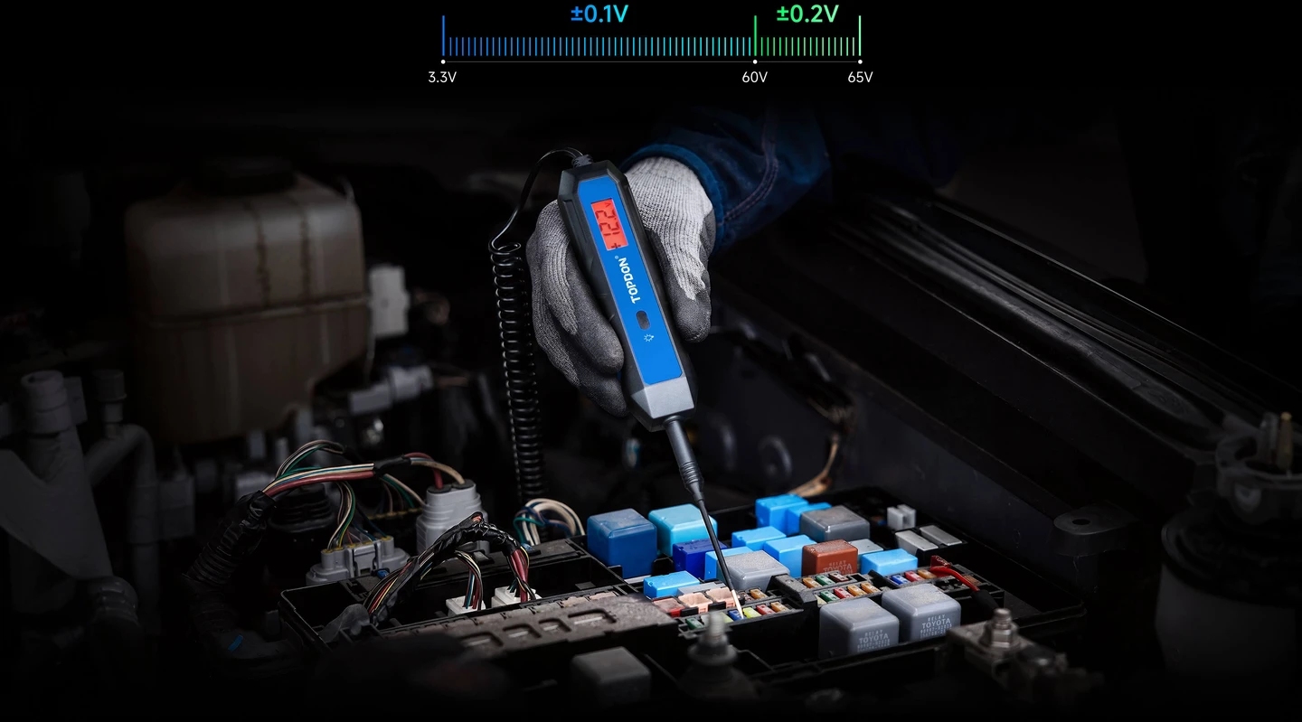
±0.1 V accuracy in the 3.3–60 V range; ±0.2 V accuracy in the 60–65 V range. Manufacturer application image.
Three basic pieces of information are gathered in the same handheld body: voltage value, polarity direction, and behavior under load in suitable circuits. Plus and minus signs with colored illumination are read along with the number on the screen. Red indicates positive, green indicates negative polarity. This display simplifies understanding the connection; it does not replace the vehicle's wiring diagram.
Numerical resolution and measurement accuracy are also different concepts. The screen displaying tenths of a volt does not mean zero measurement error under all conditions. Measuring only voltage in a sensitive sensor circuit is not the same operation as connecting a test load to the circuit.
DC measurement range
3.3–65 V
Load test range
5–30 V; max 1.2 A
Resolution
0.1 V
Accuracy
3.3–60 V: ±0.1 V; 60–65 V: ±0.2 V
Probe connection
4 mm banana connection
Cable
12.5 ft; approx. 3.8 m
Product details
Why might seeing idle voltage not be sufficient?
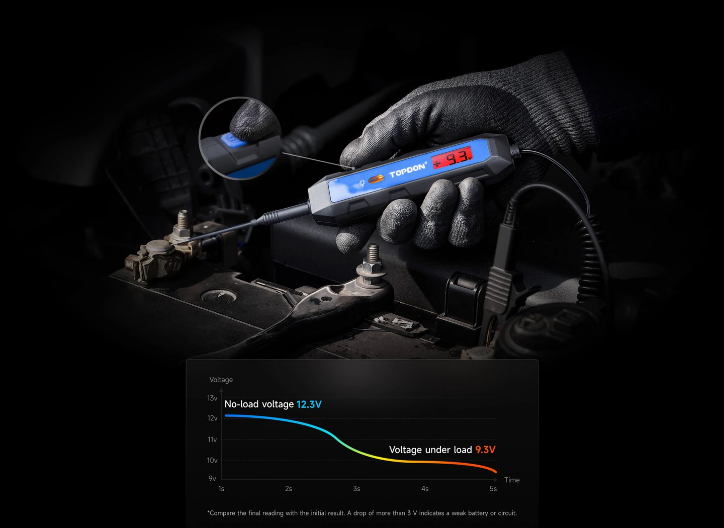
Manufacturer sample measurement; load test is limited to 5–30 V DC and a maximum of 1.2 A. The graph alone is not a battery health test result.
The presence of voltage in a wire does not solely prove that the connection can carry sufficient current when the consumer is operating. An oxidized or loose connection may behave differently under load. The manufacturer describes using the load test by pressing the button for five seconds in a suitable circuit. The purpose of the test is to examine the behavior of the supply line under load.
Since the test current is a maximum of 1.2 A, do not consider the device a load test for high-current starter motors. Although the voltage measurement upper limit is 65 V, the load test upper limit is restricted to 30 V. The two limits are not transferable; this distinction is particularly important in 36 V systems.
Product details
Long cable and interchangeable probe
The coiled test cable facilitates reaching sockets distant from the connection point. In tight spaces, you can bring the device body close to the socket and see the measurement value directly. The interchangeable probe design reduces the necessity of continuing work with a damaged or unsuitable tip.
Care must be taken not to touch the metal tips of the probe to adjacent pins, and not to damage socket seals and terminal structures. Instead of randomly piercing wire insulation to access a terminal, use the vehicle manufacturer's measurement method. The quality of contact between the clamp and probe affects the interpretation of the measurement; fluctuations due to loose contact are not considered direct component failure.
Product details
Scenario: Inspecting the fuse of a non-functioning accessory
If a vehicle outlet or light is not working, first determine under what conditions that circuit is energized. Some circuits are only powered when the ignition is on. By measuring at the test points indicated on the diagram, you can compare the status of the fuse's input and output sides.
The presence of voltage on one side and its absence on the other, or its absence on both sides, requires different investigation steps. The obtained number does not indicate the fuse's amperage rating or the health of the entire circuit. After measurement, examine the physical connections and the relevant consumer separately.
The pen's contribution is to convert the presence of power into a visually observable value.
Product details
Scenario: Voltage present at socket, but component still not working
A connected consumer may not work even if voltage is read at a power socket. In this case, measuring the connection at idle may not be sufficient. If the vehicle service procedure allows for load testing, the behavior of the line can be examined with the CT100 within the specified voltage and current limits. Compare the result with a known good connection and the same operating conditions.
If the change appears only on one side of the socket, the wire end and terminal connection can be investigated. However, applying a test load to the output of an electronic control module is not appropriate for every circuit. Do not test control unit outputs, communication lines, or sensor signals as if they were ordinary power supplies.
Product details
Scenario: Checking wire polarity and reference connection
Wire colors on a disconnected accessory may have changed over time, or a different wire may have been used in a previous repair. Instead of relying on wire color, use the diagram and measurement together. The digital display indicates positive or negative polarity relative to the reference to which the clamp is connected. The meaning of the result may also change if the reference connection at the same point is changed.
First, select a reliable reference point; then, touch the probe only to the terminal being inspected. The colored display makes it easier to distinguish polarity in poorly lit areas. This usage does not additionally determine the current the wire can carry or the suitability of the accessory to be connected.
Product details
Measurement limits and distinction from other devices
The manufacturer defines this model for automotive DC circuits. Mains AC measurement, high-voltage batteries of electric vehicles, and insulation resistance testing are not within the scope of this device's described functions. The term 12 V, 24 V, or 36 V vehicle does not mean that every connection on the vehicle can be tested.
The manufacturer's procedure is followed, especially for airbag firing circuits and sensitive electronic lines. A pulse shape requiring an oscilloscope, a communication line, or a diagnostic of an intermittent signal cannot be resolved solely by the voltage count on the screen. A change observed during measurement is a finding; it is not a result that solely identifies the faulty part.
Product details
Difference from simple test light, multimeter, and OBD device
A simple test light indicates the presence of voltage with light. This digital model combines a numerical voltage and polarity indicator with load testing in suitable circuits. When selecting a multifunctional multimeter, consider other required measurement types such as resistance, continuity, or current; these features are not implicitly assumed here.
An OBD device like the TopScan Master performs a different function by reading codes and data recorded by vehicle modules. In case of a power supply fault, OBD scanning and physical electrical measurement can complement each other. Purchasing a test pen solely to clear the engine warning light is not an appropriate choice for the task.
Product details
Package contents and maintenance
The package in the European product listing consists of the CT100 test device, a 2 mm probe, an alligator clip, an adapter, a carrying case, and a quick start guide. The manufacturer states that the device does not require separate batteries. This does not mean the measured circuit is safe or can be used at all voltages.
Before each use, check the cable, clamp, and probe for damage. After testing, store it in its case, protecting the tip. Do not let the cable contact hot engine parts or moving mechanisms. Usage conditions and warnings on the product take precedence over general automotive advice.
No. It performs DC voltage, polarity, and load tests on suitable circuits in vehicle electrical systems. A separate supported OBD fault detection device is required to access the fault memory of engine, ABS, or airbag control units.
Why are 65 V measurement and 30 V load test different?
These are two separate operating limits. The voltage indicator measures the 3.3–65 V DC range. The test applying load to the circuit is limited to 5–30 V. Being able to read voltage in a 36 V system does not mean a load test can be performed at the same point.
Does it show battery health as a percentage?
The product description does not define it as an SOH or CCA battery analyzer. Voltage and limited load testing aid electrical investigation. A dedicated battery tester is used for capacity assessment according to battery type and standard.
Can it be used on a household outlet?
No. The specified measurement range is for DC. Do not consider this range or automotive use sufficient for mains AC voltage. Mains electrical measurement requires separate, appropriate class equipment and expertise.
Does the device require batteries?
TOPDON specifies operation without requiring separate batteries. However, minimum measurement voltage and correct reference connection are important. Do not automatically assume that the absence of display means no energy is present in the measured circuit.
What is the benefit of the long cable?
The approximately 3.8-meter cable facilitates access to test points distant from the fixed reference connection. Cable length does not increase the measurement range or load test limit. The cable must be kept away from hot engine parts and moving mechanisms in the engine bay.
Comparison
Models similar to TOPDON CT100
Compare products in the same class with information on usage level, service tasks, and price.
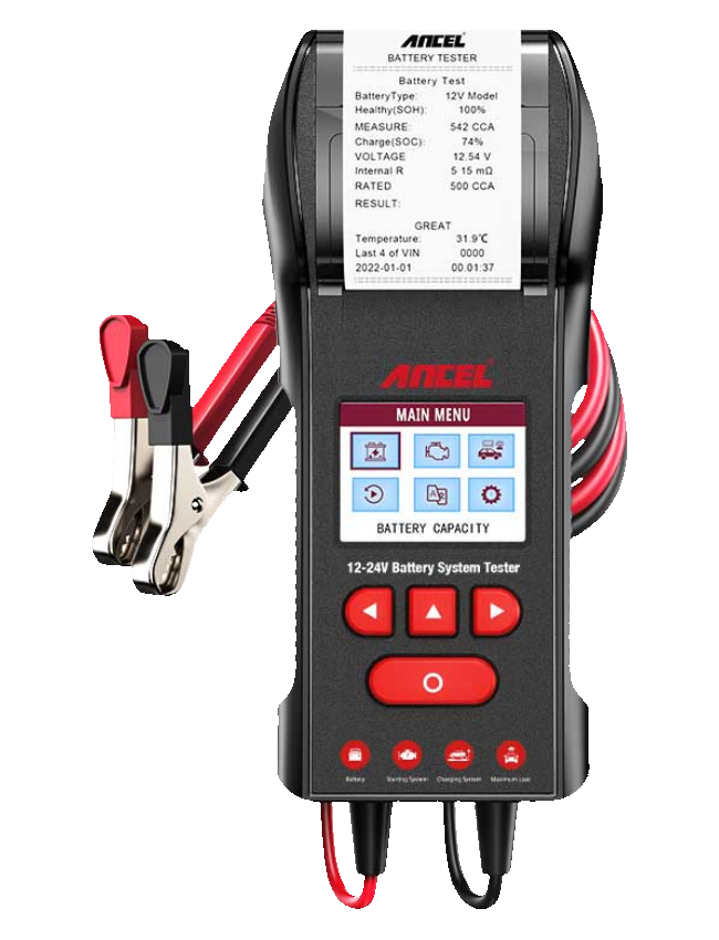
A service-type battery tester that checks battery status, starting, and charging systems in 12V and 24V lead-acid starter batteries, and provides results from its built-in thermal printer.
12V/24V battery test
Starting system check
Charging system check
≈ $1718,490 TL charged · VAT included · import duties excludedOut of stock
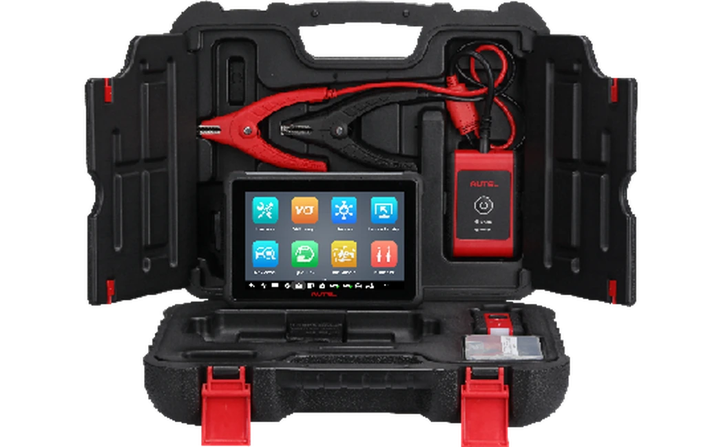
A MaxiBAS solution featuring a 7-inch Android tablet, wireless battery analysis, battery registration, electrical system diagnostics, and a service menu.
Battery health test
Cranking and charging test
Battery registration
≈ $68133,900 TL charged · VAT included · import duties excludedOut of stock