How to choose an electric vehicle diagnostic tool?
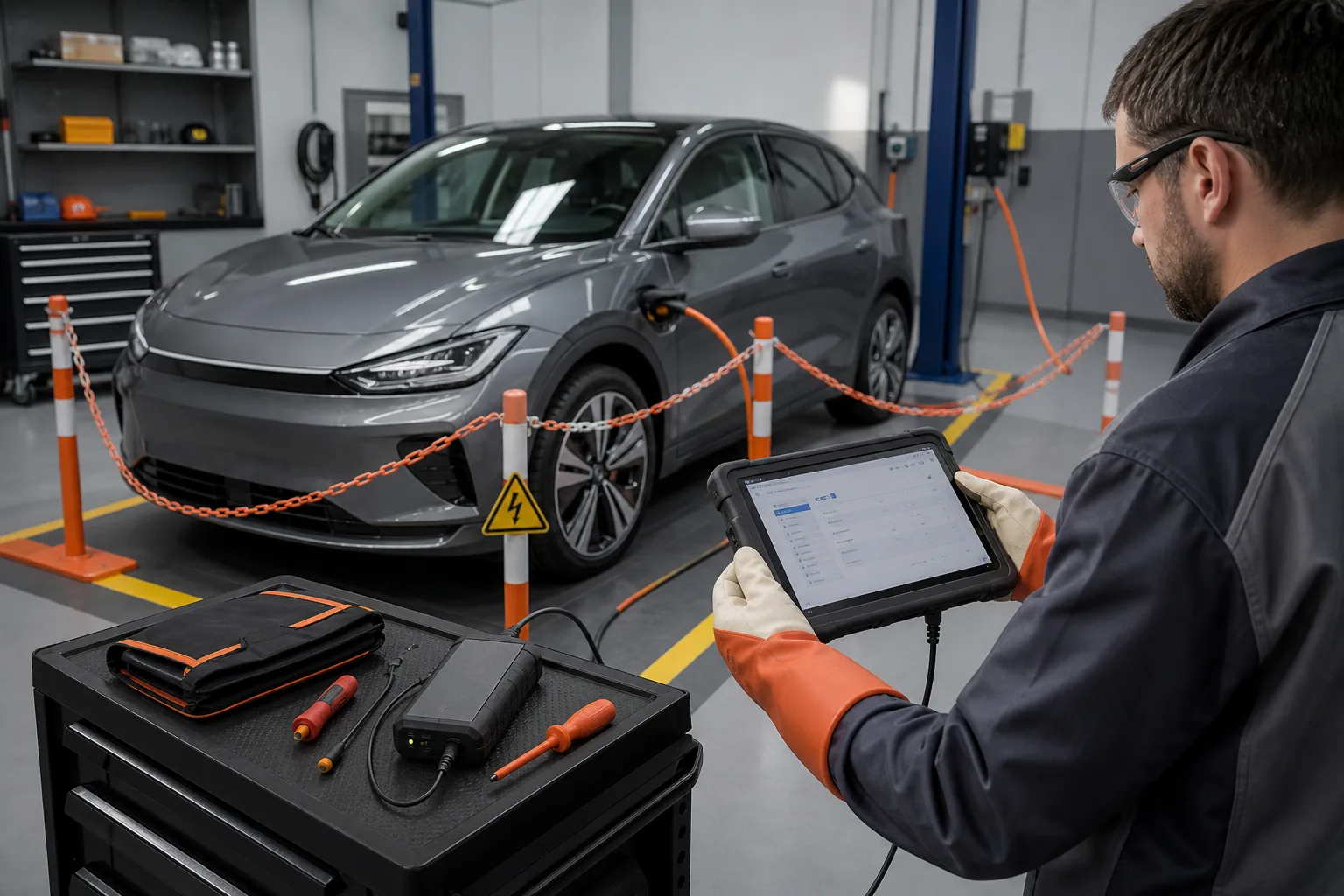
Selecting an electric vehicle diagnostic device is not just about looking for 'EV' in the product listing. The architecture of BEVs, PHEVs, HEVs, and mild hybrids, their high-voltage batteries, power electronics, charging systems, thermal management, and 12-volt networks create different service needs. A diagnostic tablet can provide fault codes and battery data; however, it does not make the high-voltage system safe and does not replace trained personnel. The right investment considers the electric vehicles coming to the service, battery pack access, measurement equipment, adapters, technical knowledge, and high-voltage operational competence together.
Why should BEV, PHEV, HEV, and mild hybrid be distinguished?
A fully electric BEV moves solely on electric power. A PHEV combines an internal combustion engine with a rechargeable battery. An HEV operates in hybrid mode without external charging; a mild hybrid may use a lower voltage support system. Control units, safety procedures, and measurements vary by vehicle type. 'Electric vehicle' is not a single diagnostic package.
In a BEV, the traction battery, inverter, electric motor, onboard charger, DC/DC converter, and thermal management are the main systems. PHEVs add internal combustion engine, fuel, and exhaust systems. The service device should be able to see the control units of both systems and the energy management between them.
HELLA's e-mobility technical guide emphasizes that different types of electric vehicles present different diagnostic and repair demands. The high-voltage battery, power electronics, motor, charging port, orange HV cables, thermal management, and low-voltage network are separate component groups.
The service categorizes the vehicle fleet into these groups. An operation that only services a hybrid taxi fleet and a specialist service diagnosing different brands of BEV batteries do not require the same device and safety investment. Target models are checked individually on the manufacturer's current vehicle and function list.
Visual summaryDiagnostic device is not safety equipment
01
Diagnostic deviceECU scan, live data, and supported service functions
02
HV safetyTraining, PPE, insulated vehicles, and de-energization verification
The tablet can provide codes and data; training, procedures, and measurement equipment to make the high-voltage system safe are required separately.
Decision guide
High-voltage safety is not a device feature
High-voltage systems in electric vehicles can pose a risk of fatal electric shock and arcing. A 'HV disabled' message on the diagnostic screen does not solely prove physical de-energization. The vehicle manufacturer's isolation, waiting, and de-energization verification procedure is applied with trained personnel, appropriate personal protective equipment, and insulated measurement tools.
HELLA states that clear competency levels, marked areas, PPE, and structured processes are necessary for high-voltage vehicle work. Occupational health, training, and operational requirements to be applied in Turkey should also be determined with current legislation and expert consultation. A foreign training class is not directly presented as a claim of local authority.
Seeing an orange cable does not mean the system is de-energized; the orange marking identifies the high-voltage circuit. The discharge time of capacitors and manufacturer-specified measurement points are waited for, even if the service plug is removed. Appropriate voltage detectors and measurement categories are used.
Damaged or crashed EVs pose different risks. If there is battery temperature, smoke, odor, fluid leakage, or mechanical deformation, the vehicle is evaluated with an isolated area and emergency plan. Normal maintenance procedures are not applied. Field safety is ensured before making a diagnostic connection.
Trained personnel
Marked safe area
Appropriate PPE
Insulated tools and measurement
Vehicle manufacturer procedure
Decision guide
Why is the 12-volt system still important in an electric vehicle?
Although the electric vehicle's traction battery is high-voltage, the 12-volt or low-voltage network is used for control units, locks, lighting, and safety circuits. A weak 12-volt battery can prevent high-voltage contactors from closing, cause numerous communication codes, and prevent the vehicle from entering the 'ready' state. Initial diagnosis begins with a low-voltage check.
HELLA explains that without a functional 12-volt system, control units related to high-voltage safety may not be controllable. Therefore, before charging the traction battery, the 12-volt battery, DC/DC converter, connections, and ground are inspected. Low-voltage history in general scans is interpreted in context.
Replacing the 12-volt battery may require registration or a procedure in some vehicles. Before interfering with the battery sensor in a high-voltage vehicle, the status of the HV system should be checked from the manufacturer's instructions. The general removal method used in internal combustion vehicles is not automatically applied.
Appropriate low-voltage power support may be required during programming or extended diagnostics. Not all operations are performed with the EV left in 'ready' state; the behavior of the DC/DC system and safety conditions vary by model. The power supply connection is made at the manufacturer-specified point.
Visual summarySystem map in EV diagnostics
Technical signals
01
HV battery and BMSPack, module, and cell data
02
Power electronicsInverter, DC/DC, and electric motor
03
Charging systemAC/DC charging and socket management
04
Thermal managementBattery and power electronics temperature control
05
12-volt networkLow-voltage system that wakes up control units
The 'vehicle not starting' complaint is not solely linked to the traction battery; the 12-volt network and control chain are also inspected.
Decision guide
How is battery pack diagnostic data read?
EV battery diagnostics are not limited to total voltage or range display. BMS error codes, pack current, contactor status, isolation information, temperature sensors, cell or module voltages, highest-lowest difference, and supported health indicators can be examined. Which parameters are provided depends on the vehicle and device coverage.
Cell voltage difference can vary based on load, temperature, and state of charge. Using a universal single threshold is incorrect. Manufacturer nominal range and test conditions are required. A momentary deviation may be related to the sensor, connection, or balancing process; records and repeat measurements are used.
SoH, or state of health, can be generated by the manufacturer's calculation model or an independent test method. The same percentage may be based on different data sources on different devices. HELLA presents basic evaluation from in-vehicle parameters and more comprehensive certified battery testing as separate solutions. The measurement method should be explained to the user.
Isolation failure is a high-risk issue. Device codes provide fault direction; they do not replace appropriate high-voltage measurement and the manufacturer's isolation procedure. Battery pack opening or module intervention is only performed with the necessary competence and equipment.
Decision guide
Charging system and power electronics coverage
The onboard charger converts AC energy to the battery appropriately; the DC/DC converter supplies energy from high voltage to the low-voltage network; the inverter manages motor drive. Charging port lock, communication, cable temperature, and station handshake can also be part of the complaint. The device should offer codes, live data, and supported tests for these modules.
In the 'vehicle not charging' complaint, home/station, cable, port, timer settings, 12-volt system, OBC, and battery temperature are separate possibilities. Controlled comparison with another station or cable can be made. Error codes and event data are recorded without deletion.
DC fast charging and AC charging may use different paths and components. If the vehicle charges on one but not the other, the diagnostic scope narrows. Parameters such as requested and actual charging power, contactor, or temperature limits may be supported in the device's live data.
Physical measurement on power electronics requires high-voltage competency. Standard multimeters or probes cannot be used. A diagnostic tablet provides safe preliminary assessment; appropriate category measurement technology is required for isolation, de-energization, and component testing.
Visual summarySafe diagnostic sequence for EV faults
01
Understand the complaint and the vehicleBEV, PHEV, HEV, and model-year
02
Classify the riskDamage, warning, and work area
03
12 V and full scanRecord the control chain
04
Manufacturer procedureOnly if competence and equipment are suitable
Before proceeding to high-voltage intervention, the scope of work, personnel competence, and the safe status of the vehicle are determined.
Decision guide
Thermal management is central to EV diagnostics
The battery, inverter, motor, and cabin climate control may use interconnected thermal circuits. Pumps, valves, fans, compressors, heaters, and temperature sensors affect range, charging speed, and battery protection. The device should scan thermal control units and provide relevant live data and safe active tests for vehicles arriving at the service.
Low charging speed is not always a battery fault; battery temperature, cooling system, or station conditions can limit power. Target and actual temperatures, pump command and feedback, valve position, and coolant circuit pressure are evaluated with technical data.
The electric air conditioning compressor may operate with high voltage. Refrigerant and oil type can be critical for electrical insulation. Air conditioning equipment and oil from internal combustion vehicles are not used without verifying compatibility. Air conditioning service training is planned in conjunction with EV safety training.
In active testing, the operation of a pump or fan indicates a physical response; it does not solely prove sufficient flow. Temperature change, pressure, and physical circulation are checked. Bleeding or filling procedures are applied per vehicle.
Decision guide
EV adapter and battery connection sets
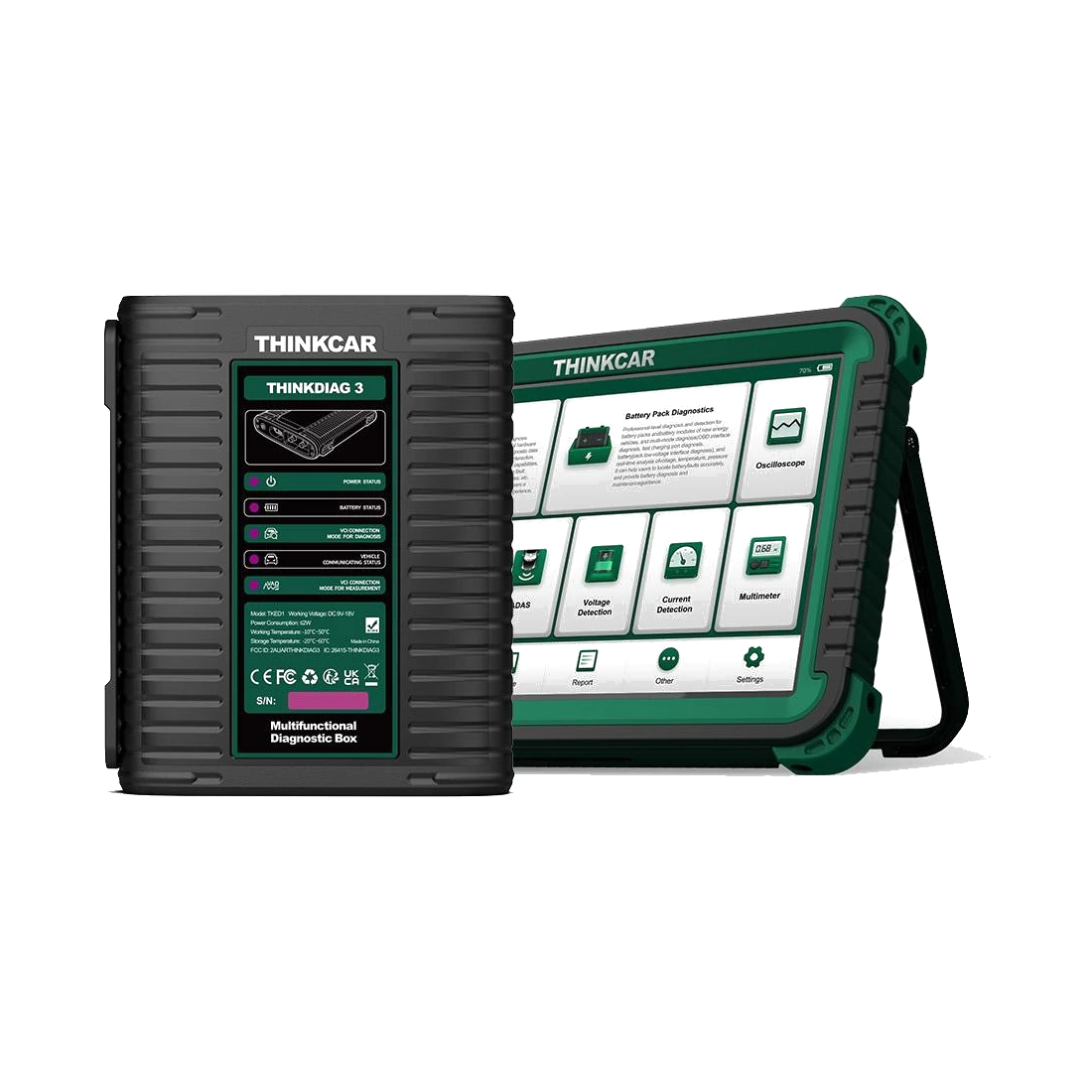
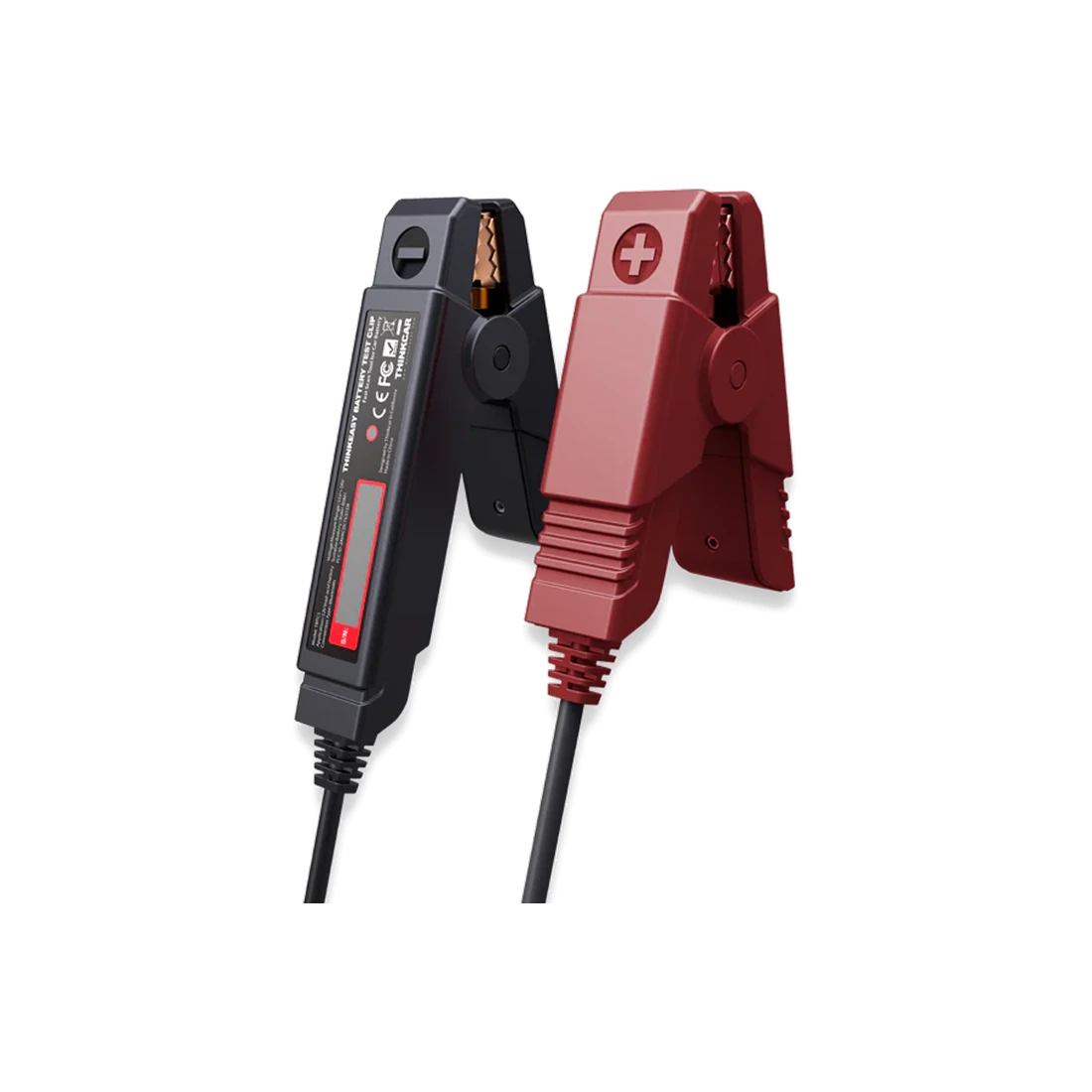
Some advanced EV diagnostic solutions may offer adapter sets that connect to the battery pack or specific test points in addition to the standard OBD connection. These connections must be vehicle-specific and used only according to the manufacturer's procedure. The physical fit of the connector is not sufficient for safe and accurate measurement.
Thinkcar CE EVD official product documentation introduces the THINKDIAG EV VCI and adapter approach for OBD and battery pack diagnostic capabilities. The specific adapters included in the purchased package, the operations they support, and the training requirements should be checked in writing.
Accessing the battery cover or service port can enter the high-voltage area. Adapters are not connected before isolation and de-energization verification are completed. Incorrect pins can cause control unit or battery damage. Cable labels and part numbers are preserved.
Adapters are checked for physical damage, insulation, and pin condition before use. Damp or dirty connections are prepared with a cleaning procedure. After use, they are stored in a safe case, and periodic inspection records are kept.
Visual summaryComplementary parts of EV service investment
01
Vehicle-comprehensive tabletBMS and power electronics access
02
Safe measurementEquipment with appropriate category and insulation properties
03
PPE and toolsProtective equipment used with training
04
Technical knowledgeManufacturer procedures and current diagrams
05
WorkspaceDemarcation, marking, and vehicle safety
Purchasing a single tablet does not create EV service competence; equipment and processes are planned together.
Decision guide
What should an EV device offer beyond full system scanning?
An EV diagnostic device should be able to display data from the high-voltage battery, power electronics, charging, thermal management, and low-voltage network in separate systems. Cell graphs, battery reports, contactor and isolation status, active tests, and service procedures should be checked on the manufacturer's current function list for the specific make and model.
While a general multi-brand tablet may offer standard full scanning on some EVs, it may not access detailed cell data of the battery pack. An EV-focused solution may provide a deeper battery diagnostic module and adapters. The choice depends on whether the service's goal is general maintenance or battery expertise.
Graphs and records help examine cell temperature and voltage differences during driving or charging. Reports should include the test condition and data source. Customers are not given context-free results like 'battery 90%'.
Technical information integration can show safety steps and connection points. However, the tablet screen does not replace official training and workshop procedures. The software being in Turkish is convenient; the accuracy of technical translation should be checked.
Decision guide
Service setup is broader than purchasing a device
Workshops wanting to offer EV service must establish training, risk assessment, marked work areas, PPE, insulated hand tools, appropriate measurement devices, lifting and battery handling equipment, fire/emergency plans, and access to technical information. A diagnostic tablet is only one part of this system.
HELLA's electric vehicle service guide lists technical competence, special tools, safety equipment, and marked high-voltage areas among the basic requirements. The operation defines what tasks it will perform: general maintenance, working on de-energized vehicles, opening battery packs, or measuring under voltage require different competencies.
Storage and shipping conditions for damaged batteries are planned separately. They are not kept on standard parts shelves. Manufacturer and local regulatory requirements are verified currently. All service personnel must know what to do in an emergency.
Insurance and professional liability coverage are checked. The customer acceptance form records the vehicle's charge status, damage, warnings, temperature, and previous interventions. Work outside the scope of competence is referred to a specialized service.
Decision guide
Electric vehicle device purchase checklist
First, list the target BEV/PHEV/HEV models and the intended work. For each vehicle, verify full scanning, BMS cell data, SoH method, isolation information, charging and thermal module access, active tests, service functions, and battery adapters separately. A total number like '80 brands' is not proof of purchase on its own.
Check new vehicle communication infrastructure like CAN FD and DoIP, gateway access, and software updates for the VCI. The EV adapter set, insulation class, and package part numbers should be included in the delivery list. If a measurement module is required, compatibility with the main device is verified.
Perform a general scan, battery live data, and a safe report on a demo vehicle. Inquire about the data source and method used for the displayed SoH result. Cell graphs, temperatures, and error codes should be readable. Exportable reports are preferred over screenshots.
The total budget includes training, PPE, insulated measurement, power supply, adapters, software licenses, and workshop layout. If the device is purchased but the safe working infrastructure is not established, EV service is not considered ready.
Decision guide
How is the battery result explained to the customer?
Battery assessment is explained according to the method used. In-vehicle BMS parameters, short diagnostic scans, controlled capacity tests, or certified battery reports are not at the same level of evidence. The result is presented along with the state of charge, temperature, error codes, and test conditions. No definitive year or mileage promise is made for remaining life.
SoC indicates the current state of charge, while SoH is an estimated or measured health indicator. The percentages are not confused. The displayed range can be affected by weather, usage, and temperature; it is not proof of capacity loss on its own.
When a cell difference is observed, it is not stated that the 'pack is faulty' without the vehicle manufacturer's tolerance and test conditions. Software updates, balancing, temperature, or sensor effects are investigated. Repair recommendations on the high-voltage pack are given only after expert evaluation.
The service report should include a clear next step: such as testing the 12-volt battery, checking the thermal system, performing a detailed battery test according to the manufacturer's procedure, or a safe expert inspection. The limits of measurement and the next steps are clearly written, rather than using fear-inducing language and absolute conclusions.
Frequently Asked Questions
Most frequently asked questions by customers
Can a normal fault detection device be connected to an electric vehicle?
Some current multi-system devices scan specific EV models. Access to the battery pack, cell data, adapters, and service functions must be verified separately for the specific make and model.
Does a diagnostic device make the high-voltage system safe?
No. The device may support the procedure; de-energization must be physically verified with appropriate training, PPE, insulated measurement, and manufacturer instructions.
Does the SoH percentage definitively indicate the battery's remaining life?
No. SoH is a health indicator that depends on the calculation or test method used. It should be explained along with temperature, state of charge, and data source.
Why is the 12-volt battery checked in an EV fault?
Control units and high-voltage contactors are connected to the low-voltage network. A weak 12-volt battery can cause numerous communication and readiness issues.
Is an adapter set necessary when purchasing an EV device?
It depends on the task. It may not be necessary for standard OBD scanning; battery pack diagnostic operations may require vehicle-specific VCIs and adapters.