Decision guide
In which area is the OBD2 socket most commonly found?
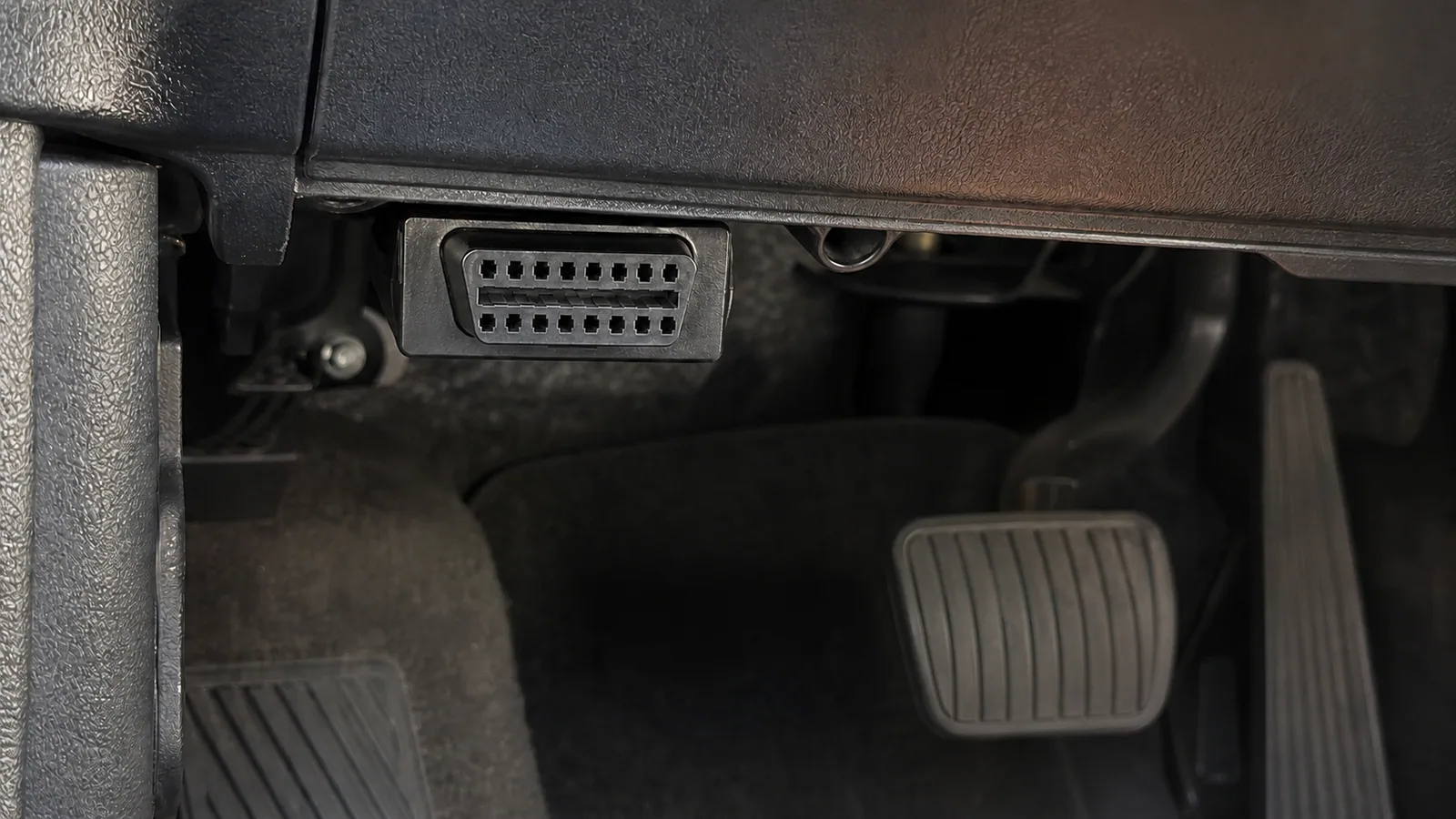
The primary area to check in passenger cars is under the driver's side dashboard. A technical report published by NHTSA states that the OBD-II connector is located under the driver's dashboard in most vehicles. This information is a strong starting point; it is not a guarantee for every vehicle.
Move the driver's seat back, park the vehicle safely, and use a flashlight to look from under the steering column towards the pedals. The socket may face downwards in some vehicles, horizontally or sideways in others. It may be behind a small plastic cover; the cover does not necessarily have "OBD" written on it. Changing your viewing angle is often faster and safer than removing trim parts.
The second area to check is around the fuse cover on the driver's side. The socket is not necessarily hidden inside the fuse box; it may be located immediately next to or under the access cover. It is important not to confuse the fuse panel with the diagnostic connection. Only the connector's shape and accessibility are examined without touching electrical connections.
On some models, the connection port may be located on the side of the center console facing the rider, at knee level, or near the small item storage compartment. Instead of directly copying photos of other models from the internet, look for terms like "data link connector," "DLC," "OBD," or "diagnostic connector" in the vehicle's own manual. The location can vary for the same model name in different body styles and production years.
- Under the steering column
- Under the pedal area trim panel
- Around the driver's fuse box cover
- Driver side of the center console
Decision guide
How to identify a 16-pin OBD2 socket?
A standard OBD connection is a data interface where the female connector on the vehicle matches the male connector on the diagnostic tool's cable. The recognized format in current passenger cars is a trapezoidal connector with a total of 16 sockets in two rows. The external shape of the connector helps determine the insertion direction.
The absence of metal contacts in every socket does not solely mean an incomplete or faulty socket. The standard defines the common functions of specific contacts and areas reserved for manufacturer use; the communication structure used in the vehicle can affect pin layout. The user should not insert metal parts into an apparently empty socket, perform bridging, or swap pins by comparing with another vehicle.
The physical presence of 16 sockets does not indicate that the device will access all control units in the vehicle. Engine emission data, ABS, airbag, transmission, body electronics, and service functions may require different software and protocol scopes. Physical fit is only the first layer; software support for the device, vehicle, and intended operation is also required.
There may be other service connectors of similar size in the vehicle. If the diagnostic device's plug does not fit easily and smoothly, recheck the orientation. Forcing the plug by tilting, wiggling, or applying excessive force can damage both the vehicle socket and the device connector. Electrical connection should not be made without determining the correct connector and orientation.
Decision guide
Safe search sequence to find the socket
The shortest path is to start with the vehicle owner's manual. If the manual provides the exact location, that information is used instead of a general internet image. If the manual is unavailable, visible areas such as the driver's side lower panel, around the steering column, near the fuse box cover, and the driver's side of the center console are checked.
Before searching, stop the engine, apply the parking brake, and put the key in a safe parking position for the vehicle. When working in the pedal area, do not leave loose floor mats, hand tools, or cables in the driving path. Perform only a visual inspection; the contact position requested in the diagnostic device's user manual is applied after the socket is found and the connection is checked.
Small covers should only be opened if their own latch or opening permits. Using a screwdriver to pry trim, pull wiring harnesses, or remove parts above the pedals is not a method for searching for a socket. If the manual describes removing parts for access, the procedure must be performed with appropriate service procedures and equipment. Forcing an unseen connection to reveal it increases the risk of damage.
Using a mobile phone camera or a small mirror to view the area behind the lower panel can be helpful. The image displays the connector shape and insertion direction on the screen; the user does not blindly insert the plug in a confined space. Nevertheless, the device should not be connected until it is certain that the part in the image is the OBD socket.
- Check the manual
- Park the vehicle safely
- Illuminate visible areas
- Verify connector with shape and orientation
Decision guide
Why does the location change between cars, motorcycles, and heavy-duty vehicles?
The OBD connection location cannot be reduced to a single template based on vehicle class. European heavy vehicle regulations allow for an accessible location next to the driver's seat as an alternative to the standard position in certain M2, M3, N2, and N3 classes. Motorcycles and other L-category vehicles have different placement and connector requirements.
In heavy-duty vehicles, the connector can be located on the cabin floor, next to the seat, or in another area chosen by the manufacturer for service access. Furthermore, the connection type and protocol may require different equipment than the simple 16-pin expectation for passenger cars. Connecting an adapter sold for passenger cars to a truck or bus based solely on physical appearance is incorrect.
European regulations for L-category vehicles define the preferred location as under the seating position; if another location is used, it requires mention in the owner's manual. This provision does not mean every motorcycle uses the same connector. Brand, model, year, engine management system, and adapter cable are checked individually during selection.
In electric and hybrid vehicles, standard emission connection and high-voltage system service procedures are not the same. Locating the OBD socket does not grant authorization to interfere with high-voltage components. Diagnostic reading must be performed within the manufacturer's safety procedures and appropriate device scope.
Decision guide
What to check in the socket before plugging in the device?
Before connecting, inspect the socket's housing, stability, cleanliness, and visible contacts. If the connector appears dislodged, cracked, wet, burnt, or bent, do not plug in the device. The plug should fit into a stable socket with the correct orientation and a straight motion.
Metal objects, contact spray, or compressed air should not be used randomly. If cleaning is necessary, follow the vehicle manufacturer's procedure for electrical connectors. Moisture or corrosion may indicate not only a connection problem but also water ingress into the vehicle. In such cases, the physical cause must be found first.
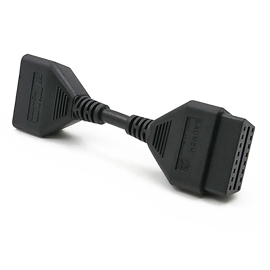
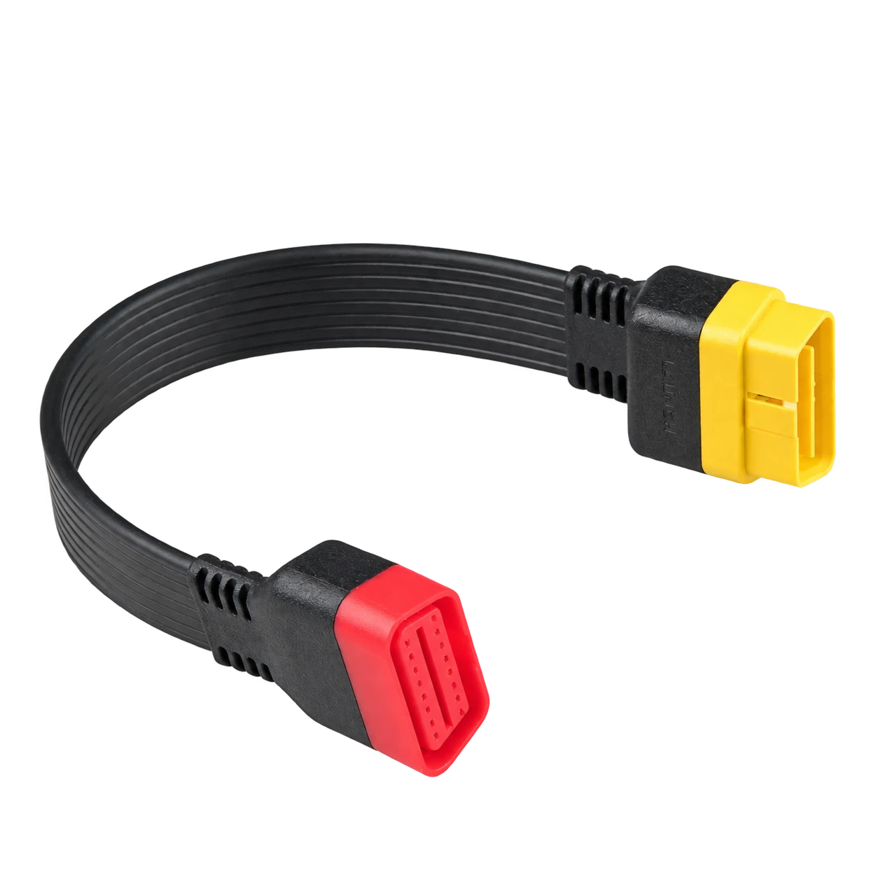
The diagnostic device's cable and VCI module should also be inspected. Bent male pins, loose cable entry, or a cracked housing can damage the vehicle socket. An adapter belonging to another connector should not be inserted unless explicitly supported by the manufacturer. Cable extensions can lead to communication and physical stress issues.
The device's instructions specify the order of connection. For some operations, the socket is connected first, then the ignition is turned on; some professional devices require additional power or VCI pairing. Coding, adaptation, and programming operations, in particular, have different power and connection requirements than simple code reading.
- No cracks or loose housing
- No bent contacts
- No moisture or burn marks
- Cable and VCI are intact
Decision guide
If the socket is present but the device has no power or connection
The device not powering on and the inability to connect to the vehicle's control unit are different faults. The first involves checking socket power supply, vehicle fuses, cable, or device hardware; the second involves checking contact position, protocol, vehicle selection, software scope, and communication lines. The same error message should not be interpreted for both situations.
If the device is not receiving any power, check the product's own power and connection instructions instead of forcing the cable again. The relevant fuse in the vehicle may be shared with another circuit; do not rely solely on a fuse number found online. Bridging or applying direct power is not permitted without the vehicle's wiring diagram and manual.
If the VCI or phone adapter powers on but ECU connection cannot be established, the phone-adapter and adapter-vehicle layers are evaluated separately. Even if Bluetooth pairing is complete, the ignition may be off, the wrong protocol selected, or the vehicle software may not be supported. The 'connected to adapter' message on the screen does not solely prove communication with the vehicle's control unit.
If looseness in the socket, a retrofitted cable, alarm system interference, or physical damage is observed, professional electrical inspection is required. Measuring communication lines, accessing airbag or security modules, and performing programming should not be attempted without the appropriate wiring diagram and expertise.
Decision guide
Does finding the OBD socket prove device compatibility?
No. The socket only indicates a physical access point. The systems a device can read depend on the vehicle's make, model, year, sales market, engine, control unit, communication protocol, and device software. The purchase decision is not complete upon locating the socket.
While a basic OBD2 scanner can access standard engine and emission codes, multi-system software may be required for ABS, airbag, or transmission. Functions like maintenance resets, electronic parking brake, battery registration, and active tests also require vehicle-specific and function-level support. '16 pin only' written in the product description does not cover these functions.
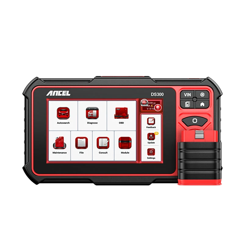
If a phone adapter is to be used, Android or iOS support, Bluetooth/BLE/Wi-Fi connectivity, the official app, and the licensing structure should also be checked. If a professional service tablet is chosen, the VCI, cable package, updates, reporting, and vehicle coverage become important. The menus offered by two devices connected to the same socket can differ.
The connection method and verified functions of the device should be read on the Otobiltek product page. For vehicle-specific functions, the manufacturer's current vehicle and function list is the basis. Price or stock information is not fixed in the guide text; current trading data on the product page is used.
Decision guide
What is the correct first step after connection?
When the socket is found, the process does not immediately start with clearing codes. The device is opened with the correct vehicle profile, connection status is verified, and existing records are read first. After the control unit, code status, freeze frame, and customer complaint are recorded, the diagnostic flow is planned.
If a simple engine code reader is used, the malfunction lamp status, stored and pending codes, and supported readiness monitors can be read. In a multi-system device, a quick scan shows which modules are accessible. Inaccessible modules are not immediately considered faulty; vehicle coverage and communication conditions are checked.
The mention of a sensor or part name in the code description does not mean that part is definitively faulty. After the socket and cable connection are completed, the actual value is to verify the code with the operating conditions, live data, wiring diagram, and physical measurements. The DTC guide explains this interpretation sequence separately.
When the operation is finished, the cable is removed from the pedal and steering movement area. Leaving the adapter permanently in the vehicle is only considered if the manufacturer defines a sleep mode and usage conditions for it. Otherwise, the device is removed after use for connection security and current consumption.