How to choose an automotive electrical diagnostic tool?
An auto electric fault diagnosis device helps read codes and supported live data from control units and execute some test commands. It does not, by itself, declare a cable, sensor, or control unit as faulty. The right device complements the systems in vehicles coming to the service, the tests to be performed, and physical measurement tools like multimeters. This guide explains the selection criteria and limitations for auto electric service providers looking for vehicle fault diagnosis device recommendations.
Match the device's function with the service's work list; the same housing or socket does not guarantee the same software coverage on every vehicle.
Work
Features to look for in the device
What the device alone cannot prove
Warning light and initial scan
Full system scan, code status, and report record
Which part the code definitively broke
Intermittent sensor/communication issue
Live data, graphs, and recording
Physical cause in supply, ground, or cable
Actuator command test
Supported active test on the relevant vehicle
That the mechanical part works correctly after the command
Electrical circuit check
Access to the correct system and operation with measurement probes
The place of multimeter or oscilloscope measurement
Module access in a new vehicle
Appropriate protocol and security gateway conditions
That every security lock will automatically open
Decision guide
What does the device show in an electrical fault?
In a modern vehicle, headlights, windows, fans, locks, climate control, charging system, and engine management can communicate with separate control units. A fault diagnosis device connects to supported control units and displays recorded error codes, status information, and some parameters. The coverage of a vehicle fault diagnosis device can vary depending on the make, model, production year, engine, hardware, and control unit software.
A fault code describes which circuit or operating condition the control unit found to be abnormal. A record like "sensor signal low" does not indicate that the sensor is definitively broken. Low supply voltage, weak ground, oxidized connector, broken wire, a mechanical problem, or a different component can generate the same code. The code is a clue as to where to start the next check.
The parameter seen by the device is not the same as the physical measurement. The control unit can filter the raw signal, combine it with other values, or use a backup value. Seeing temperature, voltage, engine speed, or key status on the screen does not automatically prove a faulty part. Unexpected values must be verified with the manufacturer's test steps and appropriate measuring instruments.
Some automotive electrical faults may leave no record or only appear under specific conditions. In this case, the absence of a fault code does not mean "the vehicle has no problem." The time the complaint occurred, scan data, and physical circuit check are considered together.
A customer complaint can be a dashboard warning, a non-functional accessory, or intermittent battery drain. Each of these requires a different module and test sequence. Recording the warnings the vehicle gives upon pickup and the conditions under which the user noticed them in the work order places the scan result in the correct context.
Which module generated the record
The current or historical status of the fault code
Supported parameters and system tests
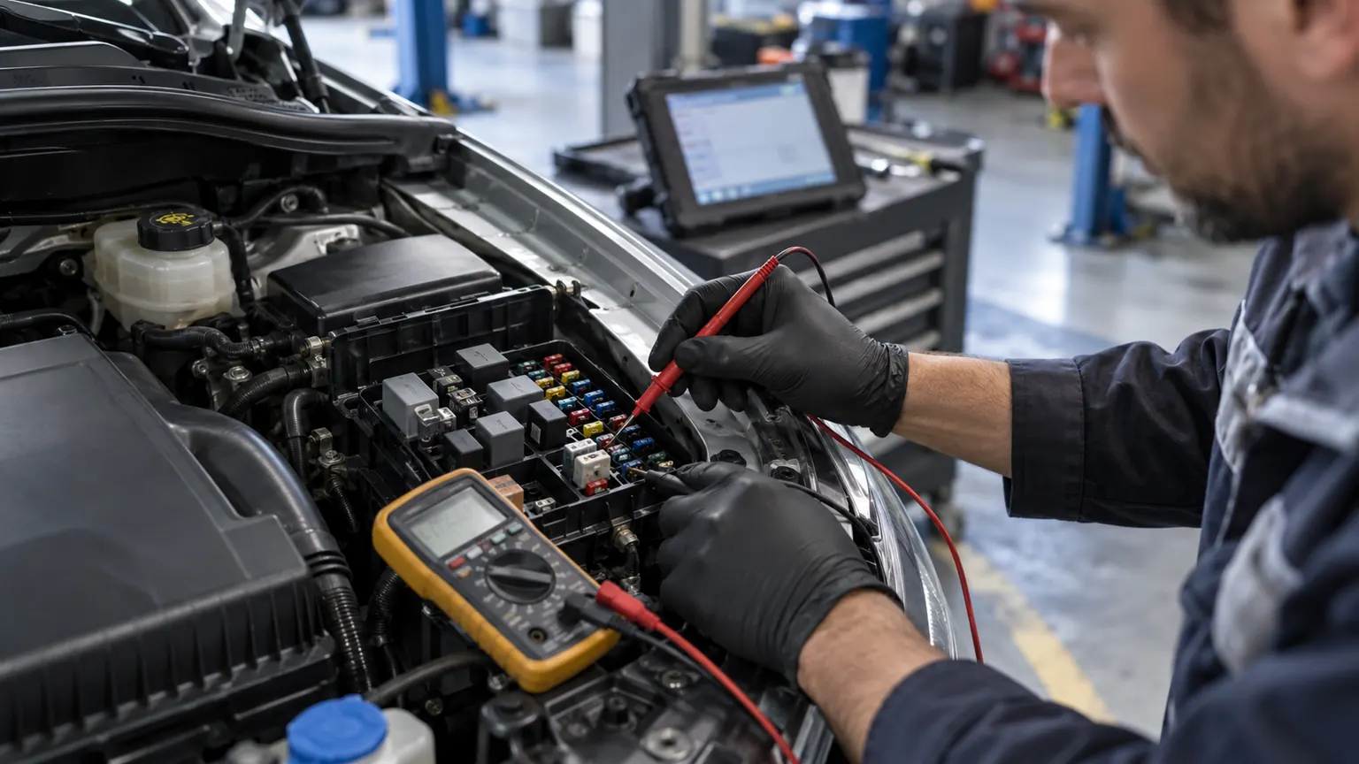
An automotive electrician is checking the power supply with multimeter probes in the fuse box
Decision guide
Start diagnosis with customer complaint and a safe initial check
Good electrical diagnosis begins before connecting a device. The technician asks which function is not working, whether the fault is continuous or intermittent, and if it changes in the rain or during a cold start. This information determines which modules and data will be prioritized in the scan. Battery condition and visible connections are also part of the initial check.
Battery terminals, main ground points, fuses, and related connectors are visually inspected. Low system voltage can cause communication codes in multiple modules. Interpreting every code in each module as a separate part failure before understanding the voltage and connection status can lead to unnecessary work and parts replacement.
Tests requiring the vehicle to be powered on or off must be separated according to manufacturer instructions. Disconnecting connectors, measuring resistance, applying external voltage to a circuit, and active testing do not have the same safety requirements. Operations on high-voltage components, especially in airbags, hybrid, and electric vehicles, should not be performed without training and service procedures.
Before the initial scan, if the battery is weak or has been recently jump-started, add this to the service note. Save the scan report without deleting it. Comparing records before and after the repair makes it easier to understand if the customer's complaint has been resolved.
Decision guide
Distinguish between full system scan and engine OBD2 scan
Standard OBD2 engine scanning provides a common starting point for emission-related powertrain data. In an automotive electrical service, a fault may also be recorded in the ABS, airbag, body, climate control, instrument cluster, steering, or another control unit. Accessing these modules requires a multi-system scan that supports the vehicle's relevant systems.
The statement "has a 16-pin OBD socket" does not indicate that every control unit will be accessible. The physical connection method and the device software's access to modules within the vehicle are different layers. Compatibility checks should be performed based on the exact make-model-year and, if necessary, engine or VIN information, for the intended operation.
During the initial scan, record the module names, code status, and communication errors. If low voltage or communication errors are observed in multiple modules simultaneously, a common power supply, ground, or network connection can be investigated. This relationship only provides a possibility; it must be verified with the manufacturer's network diagram and measurements.
A device being advertised as "full system" does not mean all functions are the same across all model years. Check that the control unit corresponding to the vehicle's model year is listed, that the code and live data can be read, and that service functions are also supported.
Engine and powertrain
ABS and SRS
Body electronics and climate control
Other modules within the vehicle's scope
Decision guide
How does live data narrow down intermittent electrical faults?
Live data helps monitor the parameters the control unit is currently seeing. If the condition that caused the fault can be reproduced, the relevant data group is selected; for example, if the complaint occurs when the headlights are turned on, the supply voltage and lighting command-related statuses can be monitored. It is not assumed that values will have the same name or scale in every vehicle.
First, select a small number of related parameters. Opening too much data can slow down the refresh rate and make it difficult to notice short-term interruptions. If the commanded value and the actual feedback can be monitored together, compare them on the same timeline.
For intermittent faults, the recording function helps the technician review the data later without constantly watching the screen. Note the test condition: cold start, headlights on, climate control active, or a specific driving condition. While the vehicle is moving, another technician should monitor the screen, or recording should be used.
If live data appears abnormal, the signal source and electrical circuit are tested separately. HELLA's sensor and actuator technical resources provide examples of how to compare fault memory, operating parameters, and appropriate electrical measurements during diagnostics. Manufacturer values and vehicle procedures take precedence.
Decision guide
When active test is useful and what it does not prove
Active test allows observing the response of a fan, relay, valve, lamp, or other actuator by sending a temporary command to a supported control unit. This function is different from the scan tool simply reading and clearing codes. When looking for an automotive electrical diagnostic tool recommendation, check the active tests that are actually used in service on a model-by-model basis.
If the expected response does not occur despite a command being issued, first verify that the test was initiated in the correct module and vehicle condition. Then, physically inspect the power supply, fuse, ground, wiring, and actuator. Seeing "successful" on the command screen does not solely prove the circuit is sound under load.
Active test options vary by vehicle and ECU; a command found for one vehicle on the same device may not appear for another. The manufacturer's vehicle coverage, software version, and the support status of the relevant module must be considered together. It should not be assumed that a test command can be issued to every component on every vehicle.
During testing, moving parts, fans, and the fuel system may operate unexpectedly. The vehicle must be in a safe position, surrounding individuals should be informed, and manufacturer procedures must be followed. Operations on high-voltage systems should not be performed with general-purpose active test assumptions.
Decision guide
Diagnostic device does not replace multimeter and oscilloscope
The diagnostic tool displays the control unit's record and supported parameters. A multimeter measures voltage, resistance, or continuity in a circuit; an oscilloscope visualizes the signal's waveform over time. These tools answer different questions. Reliable decisions in an automotive electrical service often require the combined use of scanning, circuit diagrams, and physical measurements.
When measuring with a multimeter, select the correct reference point, measurement range, and the vehicle manufacturer's test method. A wire may show correct voltage when unloaded, but a drop may occur under load. Therefore, a momentary voltage or continuity check alone does not rule out all connection problems.
An oscilloscope can help examine fast or intermittent signal changes. Without knowing the sensor type, wiring connection, and expected waveform, the trace seen on the screen alone does not lead to a "good/bad" decision. HELLA technical notes clearly distinguish that oscilloscope measurements may show signal transmission in some checks but do not solely prove the sensor is functioning correctly.
A diagnostic tool, multimeter, oscilloscope, and current clamp are not different brands of the same function. Physical measurement equipment should be included in the budget based on the typical tasks performed in electrical fault diagnosis. Evaluate device selection not by "how many faults it finds on its own?" but by how well it supports the technician's measurement workflow.
Scanner: module, code, and parameter
Multimeter: voltage, resistance, and continuity
Oscilloscope: time-dependent signal waveform
Decision guide
Check these features when buying a device for auto electrics
Do not select a device based solely on the number of brands or the total number of maintenance functions. List the vehicles and the most frequent electrical jobs serviced recently. Then, for each candidate device, verify module access, live data fields, active testing, reporting, and update conditions for the same vehicle and operation.
First, look at the scope of the full system scan. For frequently serviced vehicles, specify the need for access to ABS, airbag, body, climate control, and engine control units separately. A device listing a vehicle brand does not guarantee support for the desired control unit or special function.
For intermittent faults, selecting, graphing, recording, and sharing live data in a report is important. If active testing is required, check the function name in the manufacturer's current coverage list. General terms like "bi-directional" or "OE level" do not guarantee every test on every ECU.
Choose between wired and wireless VCI based on your workshop layout. Wireless connectivity can provide ease of movement around the vehicle; the connection method alone does not increase scan coverage. CAN FD, DoIP, and secure gateway requirements should also be evaluated based on whether they are necessary for the vehicles serviced.
Include initial software, update duration and renewal fees, adapters, warranty, support, and box contents in the purchase cost. A Turkish menu may help the technician navigate menus more easily; however, Turkish language support is not a guarantee of correct vehicle coverage or technical accuracy.
Vehicle and module coverage
Live data recording and graphing
Vehicle-specific active testing
Protocols and secure access
License, updates, warranty, and support
Decision guide
Auto ECU fault detection is different from ECU programming
A user looking for an "automotive ECU diagnostic tool" often wants to connect to the engine or another control unit and review records. This task involves reading module codes and supported data. ECU coding can change the vehicle's configuration; ECU programming involves modifying the control unit's software under conditions permitted by the manufacturer. The term "ECU tool" in the product name does not guarantee all these functions are included.
If a connection to the control unit cannot be established, do not immediately conclude the ECU is faulty. First, check the power and ground supply, relevant fuses, connection socket, network communication, and the vehicle's sleep/wake conditions. If other modules also have communication errors, investigate common network lines or power supply possibilities. Manufacturer wiring diagrams and measurement procedures should be used.
For example, if a module is inaccessible and other control units are simultaneously generating communication errors, factors such as the interface, network line, or common power supply should be investigated. If there is no connection to a single module, perform power and ground measurements according to the manufacturer's pin diagram. The diagnostic tool's "no communication" message does not mean the control unit's internal circuit has been tested.
A software update, module coding, or online operation may require a different interface, license, secure access, and stable power supply than a basic fault reader. If the process is interrupted, the module may become inoperable. Do not attempt to modify the ECU software based solely on the appearance of an option in the device's menu.
Coding configures how a module in the vehicle will operate with specific hardware and options. Programming is the process of installing or rewriting software. Listing these terms as equivalent features on a fault scanner is not sufficient information for correct selection; the required online account, license duration, power supply, and manufacturer approval must be checked separately.
Therefore, before purchasing, ask this question: Is the task reading fault codes, coding vehicle hardware, or reprogramming module software? The device and license scope for each task must be verified separately. We also explain the differences between programming, interfaces, and licenses in our separate guide.
Decision guide
Determine the device class suitable for your service profile
A user checking the engine fault light on their own vehicle does not need the same device as an automotive electrical service that deals with electrical and electronic faults daily. The difference between a basic OBD reader, a service tablet, and a professional platform lies in module coverage, live data quality, reporting, active testing, protocols, and software costs.
If basic code reading and limited engine data are sufficient for individual use, a simpler OBD2 device can be considered. If access to ABS, airbag, or body systems is desired, the product must explicitly support these modules on the relevant vehicle. A general product name like "car diagnostic tool" is not a description of functionality on its own.
For an automotive electrical workshop, regular full system scanning, live data, and module reports may be a priority. If actuator testing or maintenance functions are required for frequently encountered vehicles, these should be selected based on coverage. Circuit diagrams, manufacturer procedures, and electrical measurement equipment are also part of the workflow alongside the device.
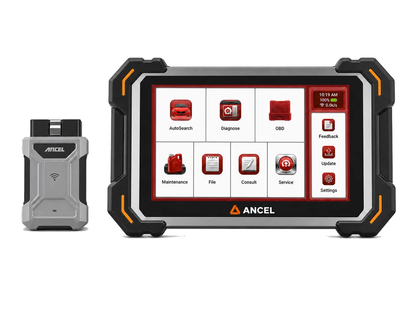
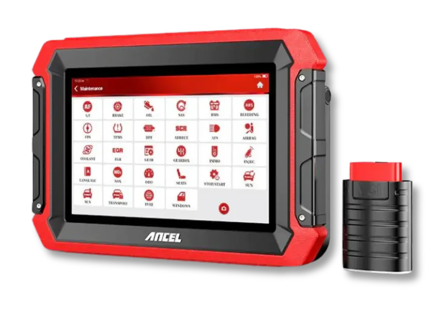
Professional tablets like the Ancel DS600 offer active tests and various service functions based on manufacturer information; the technical scope can vary by vehicle and control unit. Therefore, before purchasing, check if the active test or module scan for the makes-models-years serviced and the intended operations are listed in the current official coverage. The device does not replace physical circuit measurements.
Decision guide
Perform a short verification on the same vehicle before purchasing
When comparing multiple devices, use the same vehicle, module, and operation list. To make the question "Which device is better?" measurable, list the modules that need to be accessed and the tests that need to be performed on a few of the most frequently serviced vehicles. This way, the daily workflow is compared, not just product names.
Prepare the vehicle list by make, model, year, engine, and, if applicable, control unit. Also, concretize the test list: scan all modules, save relevant codes, open parameters to monitor, export the recording, test a specific actuator, etc. Direct questions about coverage to the seller or manufacturer with this information.
If the device offers a demo, try an initial scan, live data graphing, and report saving. Ensure the vehicle's identity or personal data is not visible in the screenshot. After the device clears the code, do not examine whether the problem is solved, but rather how the same test is repeated after the fault is rectified.
If coverage information cannot be obtained, note the ambiguity in the purchase order. The manufacturer's or authorized dealer's current official function list is more valuable than general advertising text. Do not base content or purchase decisions on claims of absolute compatibility until definite vehicle-operation support is confirmed.
If possible, test the device in your own workflow: first, get a scan without deleting existing codes, then open a frequently used live data group and save the report. Before running a common active test in service, read the manufacturer's prerequisites. This trial allows you to assess connection stability, menu language clarity, and report transferability to the customer.
Frequently Asked Questions
Most frequently asked questions by customers
What faults does an auto electric fault diagnosis device find?
It can display fault codes in supported control units and some live parameters. It cannot definitively determine on its own if a cable, fuse, ground, or part is faulty; physical inspection and measurement are required.
Does a vehicle fault diagnosis device definitively show electrical faults?
No. The code describes the condition seen by the control unit and provides a starting point for diagnosis. The cause of the code must be verified with circuit and vehicle procedures.
Is an OBD2 reader sufficient for auto electrics?
If only standard engine OBD2 data is required, a basic reader may suffice. For ABS, airbag, body, climate control, or other modules, multi-system coverage specific to the vehicle is needed.
Does active test work on every vehicle?
No. Active test support can vary by make, model, production year, control unit, and software version. The desired command should be checked against the current vehicle coverage.
Does a diagnostic device replace a multimeter or oscilloscope?
No. A diagnostic device measures module and parameter information; a multimeter and oscilloscope measure the electrical behavior of a circuit. These tools complement each other in auto electric diagnostics.
What should I look for when choosing an auto electric fault diagnosis device in Turkish?
In addition to the Turkish menu, check for correct vehicle and module coverage, live data and recording functions, active test support, update conditions, and warranty information. Language support does not guarantee coverage.
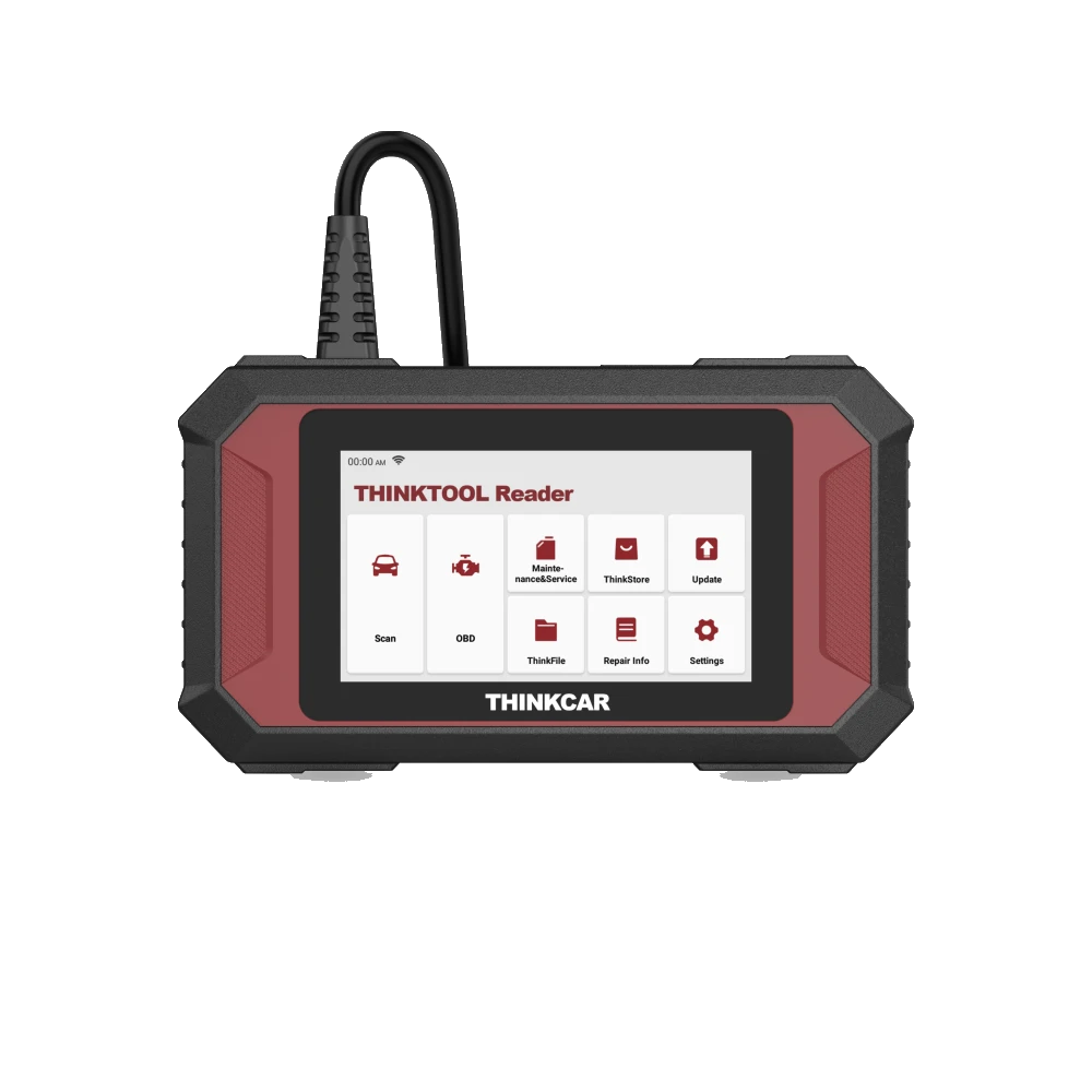
Thinktool Reader 7 is a 5-inch wired device that reads codes and live data in seven vehicle systems, offering seven maintenance functions from 28 options.