Product information
What does the Scania VCI3 SDP3 Diagnostic and Programming Device do?
Scania VCI3 is the communication interface between the diagnostic software running on a computer and the vehicle; it is not a standalone diagnostic device with a screen. Scania's current RMI page indicates that SDP3 requires a standard PC, SDP3 software, a license key obtained through TIS, and a VCI.
The same source explains that SDP3 can be used with trucks and buses from series 3 to series 6, and that SWS is gradually replacing SDP3. According to Scania's SWS documentation, VCI3 can be used on certain truck and bus series without cybersecure electrical systems; VCI4 is required for communication with new cybersecure vehicles.
Therefore, the product is not offered as "full authorized service operation on all Scania vehicles." The physical identity of the hardware, connection method, software license, and vehicle generation are checked separately.
Vehicle Coverage
Which vehicles does the Scania VCI3 SDP3 Diagnostic and Programming Device support?
The make name alone does not guarantee compatibility. Within the same make, model year, engine, chassis, control unit, communication protocol, and intended operation can yield different support results.
- Vehicle Group
- Light, medium, or heavy commercial vehicle classes included in the product software
- Supported makes
- Scania
- Supported models
- Trucks, buses, and engine families; verified by SDP3 version, VCI hardware, and control unit.
- Scope of service
- Code reading, live data, active test, service function, coding, and programming may be supported separately.
- Connection conditions
- Distinction between aftermarket VCI3 type product and official Scania VCI identity, Vehicle series, production year, and cybersecure electrical system status, Separate provision of SDP3/SWS software, license, and user authorization, USB, WLAN, serial, and firmware check on the shipped physical unit, Power supply and recovery procedure before programming
- The make and model examples on the page do not guarantee all production years and all functions.
- Before any definitive operation, the manufacturer's current coverage record must be verified with the VIN or full vehicle information.
Open official sources and coverage connectionsProduct details
What does the Scania VCI3 device do?
The VCI3 type interface transfers data between the vehicle's electronic control units and the appropriate Scania diagnostic software running on a Windows computer. On supported vehicles and control units, fault memory, live values, component tests, control unit information, parameters, calibrations, and programming flows permitted by the manufacturer's procedure can be viewed.
The device is only the communication layer; it does not automatically diagnose faults and does not generate software licenses. The technician must verify the fault code with circuit diagrams, physical measurements, and service instructions.
- Reading and clearing fault codes for supported errors
- Viewing live data and control unit information
- Tests, parameters, and calibrations on supported systems
- Programming communication if authorization and procedure exist
Product details
Is this product an original Scania VCI3?
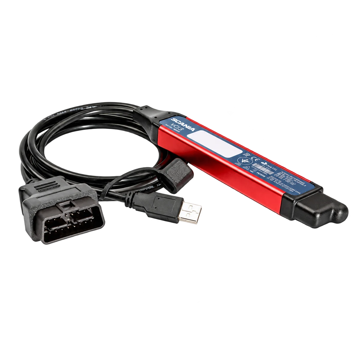
The red-blue housing, CAN/INFO/ERROR/WLAN/POWER indicators, and VCI3 layout in the visuals follow the Scania VCI3 design. However, the photos do not present an official dealer invoice, verifiable Scania part number, serial record, or manufacturer supply document. The phrase "original quality" in the file name is not technical proof.
Therefore, the product identity is clearly stated as an aftermarket VCI3 type interface. Before shipment, the physical device's label, serial information, USB connection, WLAN behavior, and VCI information within SDP3 should be recorded.
- Sales identity
- Aftermarket VCI3 typeClaims of OEM or official Scania dealer product are not used.
- Visible connections
- USB and vehicle cableThe physical ends in the gallery are used as a basis.
- WLAN
- Unit-based checkThe indicator label alone is not proof of wireless functionality.
Product details
Why is SDP3 software and license required separately?
Scania's official diagnostic page states that SDP3 usage requires a standard PC, SDP3 software downloaded from TIS, a license key connected to the computer, and a VCI. Purchasing the VCI3 hardware does not automatically grant an up-to-date SDP3 license, TIS access, or online programming rights.
Modified software offered online as "latest version," "lifetime," or "full online" does not substitute for an official license and up-to-date vehicle data. The sales package for this product does not include a computer and software license.
- SDP3 software is a separate component from the hardware
- License key can work via TIS and connected to the computer
- Online access requires separate authorization
- Version number alone is not a guarantee of vehicle/operation
Product details
Which vehicles does Scania VCI3 work on?
Scania states that SDP3 can be used on trucks and buses from series 3 to series 6.
In the current SWS document, VCI3 can be used on P, G, R, and T series trucks, L, P, G, R, and S series without cybersecure electrical systems; and on certain F, K, N, and non-cybersecure C/K series buses. This list does not mean the device unlocks all functions on all model years.
Verification must be done with the chassis number, vehicle series, production date, electrical system, and control unit to be worked on.
- Trucks: P, G, R, T and conditionally L/P/G/R/S
- Buses: F, K, N and conditionally C/K
- Check VCI4 requirement if cybersecure electrical system is present
- Engine, industrial, or marine applications require separate license/scope verification
Product details
Difference between VCI3, VCI4, SDP3, and SWS
VCI3 and VCI4 are physical vehicle communication interfaces; SDP3 and SWS are diagnostic environments running on a computer. Scania states that SWS is gradually replacing SDP3 and is the primary solution for new cybersecure vehicles. Official SWS documentation states that only VCI4 can communicate with new cybersecure vehicles and power systems.
Therefore, before purchasing VCI3, it must be determined whether the vehicle requires the older SDP3 scope or the SWS/VCI4 scope.
- VCI3/VCI4: hardware between vehicle and computer
- SDP3/SWS: diagnostic software and workflow
- New cybersecure vehicles: VCI4 and SWS are prioritized
- VCI3: can be used on supported non-cybersecure vehicles
Product details
How are USB and WLAN connections evaluated?
The official VCI3 user manual explains that a WLAN profile can be established directly or via an existing network, the device can be searched in SDP3 by its serial number, and drivers can be installed on the first connection. However, it cannot be determined from the casing appearance alone whether the aftermarket unit on sale has the same wireless hardware and firmware.
During the initial acceptance test, first check the USB connection, then the WLAN network, device serial visibility, and the SDP3 VCI information screen. Use the most stable and verified connection during programming.
- First, test device and driver recognition via USB
- WLAN SSID, connection, and serial number check
- Recording of VCI information screen within SDP3
- Uninterrupted connection during critical write operations
Product details
Diagnostic, calibration, and programming limitations
Competitor pages often contain broad statements like "performs all operations completely" or "provides full access to all Scania systems." Such scope cannot be verified based on the hardware name. The actual operation list depends on the vehicle's control unit, SDP3/SWS version, license, user authorization, and Scania service procedure.
Clearing a fault code is not the same risk level as uploading ECU software. Before parameterization, SOPS, calibration, or programming operations, record current values and perform a full vehicle scan.
- Reading, clearing, testing, calibration, and programming are separate capabilities
- SOPS or parameter operations may require authorization and vehicle data
- Backup/record taken before operations on critical modules
- No definitive compatibility promise is made for unverified functions
Product details
Power and data security before programming
Voltage drop in the vehicle, computer going to sleep, or disconnection of USB/WLAN during data writing to the control unit can render the module unusable. Use an external power supply according to the manufacturer's procedure; connect the computer to an adapter, disable sleep and USB power saving, and secure cables.
Record the chassis number, control unit ID, current software level, and fault scan before the operation. Do not start critical write operations without a recovery plan.
- Stable vehicle supply and appropriate programming power source
- PC connected to adapter and sleep/USB saving disabled
- Vehicle scan and module ID recording before operation
- Rescan and function test after operation
Product details
Package contents of the Scania VCI3 type device
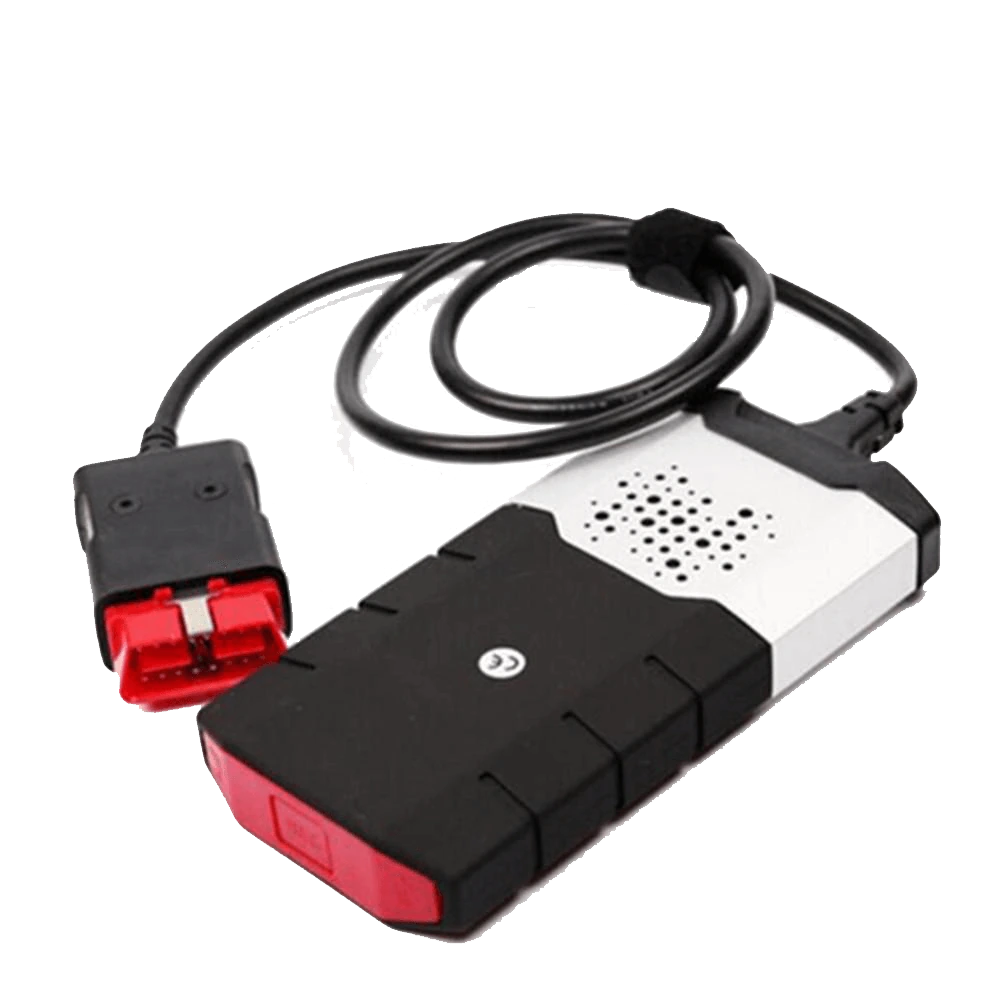
The gallery shows five actual devices from the same product family. The photos show the VCI3 type interface, fixed vehicle connection cable, vehicle connector, and USB end. A laptop, carrying case, separate adapter, license card, or software memory are not included as they are not shown in the standard package visual.
The backgrounds have been made transparent; the product's shape and physical parts have been preserved. Before shipment, the device, cable, connector, USB end, and serial information should be recorded with a photo.
- 1 aftermarket Scania VCI3 type interface
- Vehicle connection cable and connector attached to the device
- USB computer connection end
- Computer, software, and license are not included in the package
Product details
Initial diagnostic flow for a Scania vehicle arriving at the service
Upon vehicle acceptance, record the driver's complaint, warning lights, last maintenance or repair information, and the conditions under which the fault occurred. Before connecting the VCI3, check battery voltage, diagnostic socket, visible wiring damage, and fuses. Open the correct SDP3 environment on the computer; if the vehicle is not recognized automatically, verify the chassis and product information.
In the first step, scan all accessible control units and save the results without modification. Read active and historical fault codes along with their occurrence time, counter, environmental conditions, and related live data. Clearing fault codes is not diagnostics; clearing should only be done after recording and completing basic electrical/mechanical checks.
After repair or part replacement, apply necessary calibration, rescan the vehicle, and perform a functional test under the same operating conditions. Thus, the VCI3 is used not just as a code clearing tool, but as a communication layer for a documentable service procedure.
- Record customer complaint and vehicle history
- Visually inspect battery, socket, fuses, and wiring
- Export initial full scan without modification
- Verify fault code with live data and physical measurement
- Perform rescan and road/functional test after repair
Product details
Sequence of checks if VCI3 does not connect or vehicle is not visible
If the POWER light is not on, first check the supply and ground at the vehicle socket, cable, and connector. If the computer does not see the device, try a different USB port; check for driver errors and power saving in Windows Device Manager.
If WLAN cannot be found while USB connection is working, check the device's wireless hardware, region settings, SSID, network profile, and firewall. If the ERROR indicator is on or disconnections occur repeatedly, do not start programming.
Cross-checking with another computer or a known working vehicle helps to isolate whether the problem is with the interface, the computer, or the vehicle side. Serial number, firmware information, SDP3 version, screenshots, and LED behavior should be added to the support record.
- No POWER: supply, ground, socket, and cable
- No USB: port, driver, and Windows power settings
- No WLAN: SSID, region, network profile, and firewall
- No Vehicle: contact, CAN line, vehicle generation, and software scope
- If disconnected, cross-check before programming
Product details
How to perform device acceptance test upon delivery?
The device body, fixed cable, vehicle connector, and USB tip are compared with the gallery view during package opening. If there is cable crushing, pin bending, loose body, oxidation, or label erasure, the device is recorded before connecting to the vehicle. The serial and product label are added to the order document.
In the first electrical test, it is checked that power is supplied from the vehicle socket and the POWER indicator behaves correctly. Then, USB recognition on the computer, driver, SDP3 VCI information, and WLAN connection, if available, are tested. On a test vehicle, read-only and full scans are performed; calibration or programming is not initiated without observing communication stability.
When the acceptance test result is saved along with the computer and software version used, the hardware, software, and vehicle side can be more quickly differentiated in subsequent support requests.
- Physical body, cable, pin, and label check
- Serial number and shipment record matching
- USB, driver, and SDP3 VCI information test
- First vehicle communication attempt with read-only