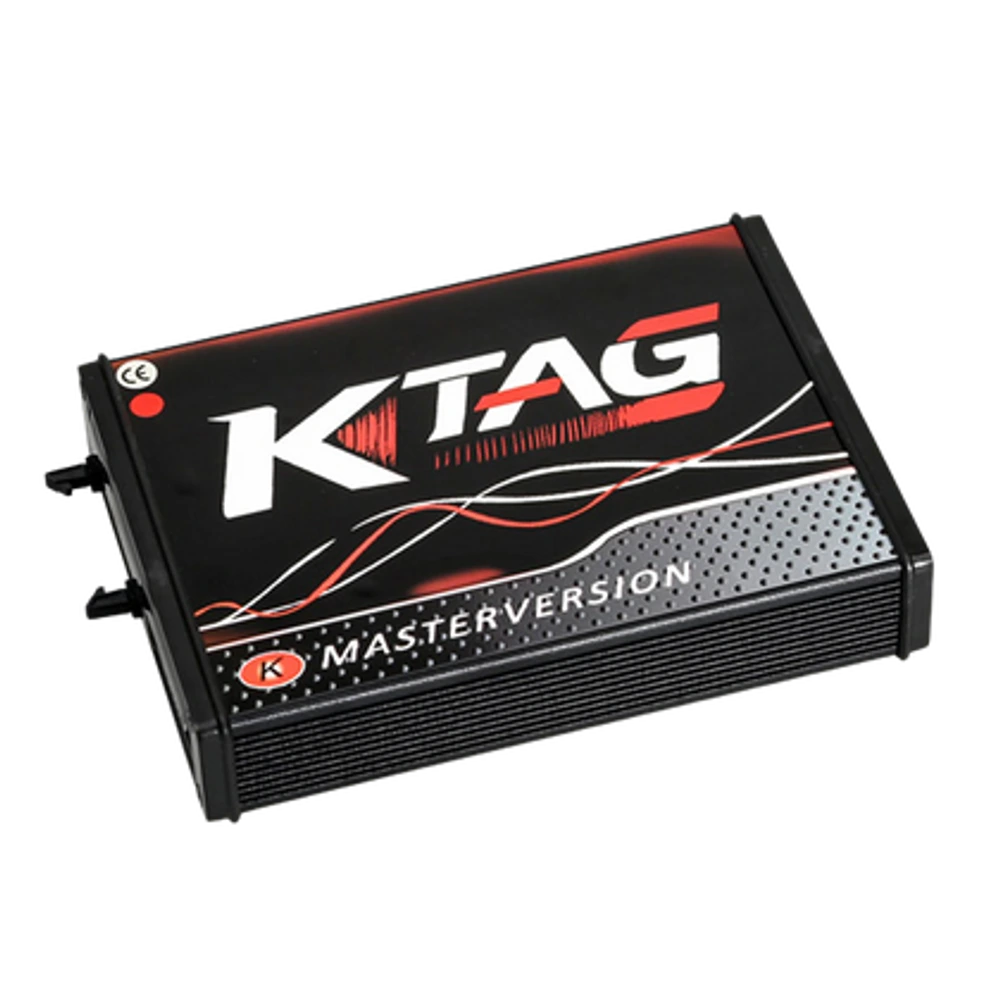
Product information
What is the Xhorse Multi-Prog ECU TCU and EEPROM Programming Device used for?
The Xhorse Multi-Prog XDMPG0GL is not a general-purpose service tablet for scanning vehicle faults; it is a professional programmer that works with data from supported ECUs, TCUs, EEPROMs, MCUs, immobilizers, and instrument clusters. Before performing read, write, or clone operations, the full module number, processor, connection method, and current software scope must be verified.
Vehicle Coverage
Which vehicles does the Xhorse Multi-Prog ECU TCU and EEPROM Programming Device support?
The make name alone does not guarantee compatibility. Within the same make, model year, engine, chassis, control unit, communication protocol, and intended operation can yield different support results.
- Vehicle Group
- ECU, TCU, MCU, or EEPROM families found on the manufacturer's current protocol list
- Supported makes
- Multi-brand coverage; the current make list is obtained from the manufacturer's official vehicle or protocol database.
- Supported models
- Verified from the official coverage screen based on make, model, model year, engine or chassis, and control unit.
- Scope of service
- Code reading, live data, active test, service function, coding, and programming may be supported separately.
- Connection conditions
- XDMPG0GL global version, Current module and operation list, Correct cable or adapter, Stable power and backup procedure
- The make and model examples on the page do not guarantee all production years and all functions.
- Before any definitive operation, the manufacturer's current coverage record must be verified with the VIN or full vehicle information.
Open official sources and coverage connectionsProduct details
What is Xhorse Multi-Prog used for?
Multi-Prog is used to read and save memory or processor data on electronic control units, write supported files, and clone modules with appropriate source-target matching. ECU refers to engine management, TCU refers to transmission management; EEPROM and MCU are different data storage and processing layers within the module.
The device's function is to access these layers using the manufacturer's specified connection method. It does not replace diagnostic tablets focused on fault code scanning, live data, or maintenance resets.
For a cloning job, simply having the physical socket fit is not enough; the hardware family, part number, processor type, software version, and security data of the source and target modules must be compared individually. Saving the read file completely, creating a revert copy before writing, and performing verification at the end of the operation are part of the workshop process.
- Reading, writing, or cloning supported ECU and TCU data
- EEPROM and FLASH memory operations
- Supported operations on MCU, immobilizer, and instrument cluster module data
- File comparison, checksum, and verification tools
Product details
Verified main functions and operating limits
Xhorse product information lists read, write, and clone operations for ECU and TCU, as well as read-write functions for MCU, immobilizer, EEPROM, FLASH, and instrument cluster data for Multi-Prog.
The product family also mentions BMW ISN reading, MED17/EDC17 data processing, checksum correction, file comparison, device self-test, intelligent error guidance, and online updates. These items alone do not guarantee operation for any specific vehicle or module.
Definitive support is shown in the Multi-Prog software by selecting the manufacturer, module family, part number, processor, and operation type. Since the support list can expand with updates or an operation method may change, the current screen in the device software should be used instead of a list on an old sales page.
The presence of third-party plugin support does not mean that every plugin is developed or approved by Xhorse; the source of the script and file used should be checked separately.
- Scope depends on the exact control unit and operation type, rather than the vehicle name
- Bench, boot, OBD, and direct chip operations are different
- The current software screen replaces the old static support list
- Save the source file and connection diagram before writing
Product details
Difference between Bench, Boot, OBD, and 48-pin socket
In bench operation, the control unit is removed from the vehicle and connected to the specified pins using an ECU or MCU cable. Boot method may require access to specific points on the module board; incorrect pins, reverse power, or missing ground connections can damage the control unit.
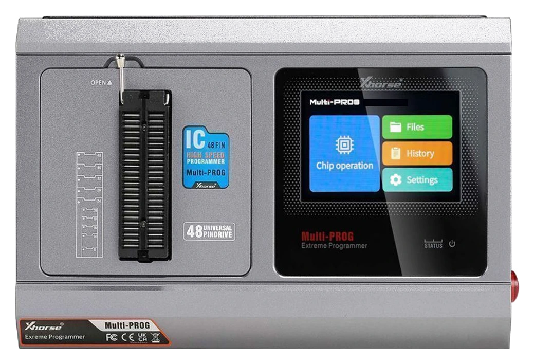
Supported OBD operations communicate via the vehicle socket, but having the product's OBD cable does not mean all modules can be written on the vehicle. The 48-pin universal socket works with integrated circuits where the correct package and orientation information is available.
The technician first identifies the module label and the processor on the board, then matches the cable with the diagram in the software. Writing is not initiated without reading the connection diagram on the screen, power requirements, and operation warnings. The choice of soldered or solderless adapter also varies by module family; optional boards are not assumed to be included in the standard package.
- Bench: Pin connection to a removed module
- Boot: Specific access and trigger points on the board
- OBD: On-vehicle operations supported only by the software
- 48-pin socket: Direct chip operation with correct orientation and package
Product details
Technical specifications
The XDMPG0GL global version combines a Linux-based operating environment, ZYNQ7020 dual-core Cortex-A9 and FPGA architecture, a 3.5-inch screen, and USB and RJ45 connections. The manufacturer's package uses a 15V / 4A power adapter.
Published technical information indicates an approximate operating current of 300 mA at 14V, an operating temperature range of -20 °C to +50 °C, a storage temperature range of -30 °C to +65 °C, and device dimensions of 233 × 150 × 54 mm.
These describe the device's laboratory or workshop setup; they do not replace the power supply required by the programmed module itself. The USB connection is used for computer software and data transfer, while the RJ45 connection is used for network functions. The screen on the device provides access to files, history, settings, and supported chip operations.
System requirements and language options for the current software should be checked before installation.
- Model code
- XDMPG0GLGlobal version product code
- Processor
- ZYNQ7020 dual-core Cortex-A9 + FPGA
- Screen
- 3.5-inch
- Power
- 15 V / 4 A adapter
- Connectivity
- USB and RJ45
- Dimensions
- 233 × 150 × 54 mm
- Operating temperature
- -20 °C to +50 °C
- Storage temperature
- -30 °C to +65 °C
Product details
How is ECU and TCU scope checked?
Published Xhorse support lists include examples from VAG SIMOS, Bosch MED17/EDC17, MG1/MD1; BMW MSD/MSV and some Bosch engine control units, as well as TCU families such as DQ200, DQ200, VL381, DL501, DKG, VGS, MPS6, and ZF 9HP.
These names represent broad families; it cannot be concluded that all hardware and software versions within the same family are supported by the same method. Before purchasing, record the front and back label photos of the module, manufacturer part number, Bosch/Continental/Delphi/Marelli number, processor information, and the intended operation.
Then, navigate to the same path in the Multi-Prog software; check if the desired operation such as read, write, clone, checksum, or ISN is individually available. The presence of only read in a menu does not imply that writing is also supported. The current connection diagram, required adapter, and any additional license conditions must be verified together.
- Module manufacturer and full part number
- Processor or memory family
- Desired operation: read, write, clone, checksum, or ISN
- Connection method and required adapter shown in the software
Product details
Initial setup, account matching, and update
Start the setup before connecting the device to a control unit. Download the current Multi-Prog installation package from the Xhorse software source; run the installation file, select the destination folder, and wait for the driver installation to complete. When the program opens for the first time, check the computer's network connection.
Connect the main device to the computer using the USB cable from the box; after the software recognizes the device, complete the Xhorse account matching with the serial number and global version information. In the "Update Online" section, first check the software and database, then check the firmware version while the device is connected. USB, network, or device power should not be interrupted during the update.
Then, run the device's self-test and verify that the connection units do not report errors. If functions dependent on account connection, such as MQB48, are to be used, check the corresponding VVDI2 Full or Key Tool Plus record and license screen on the same Xhorse account separately.
Before the first module operation, open the ECU or TCU menu to be worked on; verify the current connection diagram, cable, adapter, and the operation type offered by the software together. If the installation package, driver, or update screen appears different from a previous version, do not proceed based on the old screen; follow the instructions in the current software.
- Install the current Multi-Prog software and complete the driver installation
- Verify the serial number and global version after USB connection
- Check software, database, and firmware updates sequentially
- Run device self-test and review error log
- Match module diagram, cable, adapter, and operation type before the first read
Product details
Safe workshop workflow before programming
The work order begins with the module ID, vehicle information, and the customer's desired outcome. Before removing the module, the vehicle's fault and communication status are recorded. Electrostatic discharge precautions are taken at the workbench; pins are inspected under magnification, and the power supply's voltage and current limits are set according to the connection diagram.
The first successful read is saved in two separate locations without any changes, and the file size and checksum result are noted. If a target module is to be used, its hardware number and processor family are compared with the source module. During writing, the cable, computer, network, or power connection is not interrupted.
Once the operation is complete, the software's verification step is run; after the module is reinstalled in the vehicle, communication, fault codes, and related functions are checked again. Multi-Prog is a powerful programmer, but it does not replace a proper backup and rollback plan.
- ESD-protected, clean, and dry workspace
- Correct pin diagram and current-limited stable power
- Two separate backups of the unchanged initial read
- Post-write verification and final on-vehicle check
Product details
Reference package contents
The common list published for the global package includes: Multi-Prog main device and VH13 adapter, 15V / 4A power adapter, power cable, USB cable, MCU cable, MCU DB15 cable, ECU cable, ECU DB15 cable, OBD cable, VH20 and VH24 interface boards, and five spare ECU cable connectors.
The actual package view in the gallery helps distinguish these basic parts. Plug type or minor revisions may vary by region, so the delivered set should be counted individually upon unpacking.
Solderless special adapters sold for MQB, EIS, BCM, ECU, or chip families are not included in the standard package unless explicitly stated in the product description. A carrying case, additional laptop, laboratory power supply, and third-party data services are also not included in the standard list.
- Multi-Prog main device and VH13 adapter
- 15 V / 4 A adapter, power and USB cables
- MCU and ECU cables and DB15 interface cables
- OBD cable, VH20 and VH24 boards, five connector spare parts
Product details
Key difference between Multi-Prog and VVDI Prog
Multi-Prog is the next-generation programmer positioned by Xhorse after VVDI Prog. It consolidates functions such as ECU and TCU read-write-clone, built-in screen, online updates, self-test, intelligent error guidance, checksum, and file comparison on a single platform. However, it should not be assumed that all adapters purchased for the old VVDI Prog will fit directly.
Xhorse technical descriptions indicate that an additional multi-function adapter, such as XDKP30, may be required for some old adapters to be used with Multi-Prog. When making a purchase decision, the module work to be performed, existing adapter inventory, and the current software list should be compared, rather than just the term "next-generation."
In scenarios requiring key learning or final on-vehicle matching, another Xhorse device such as VVDI2 or Key Tool Plus may be additionally required; Multi-Prog is not a general-purpose key device that completes the entire immobilizer process on its own.
- Next-generation hardware, screen, and direct update workflow
- Usage focused on ECU/TCU cloning and data processing
- Direct compatibility not assumed for old adapters
- Additional device may be required for on-vehicle key learning
Product details
MQB48 function, account matching, and additional licenses
Xhorse product description mentions the MQB48 license with Multi-Prog and states that supported NEC35XX functions can be shared with VVDI2 Full or Key Tool Plus devices connected to the same Xhorse account. This information does not mean that key operations for all MQB vehicles are completed solely with Multi-Prog.
While Multi-Prog is used to read module data, key preparation or on-vehicle learning steps may require another device, account, or online service. Upon receiving the device, the serial number is linked to the Xhorse account; the software and license screen are recorded.
A function that appears free may have regional, account, device model, or per-operation service conditions that can change over time.
- Xhorse account and device serial number matching
- Checking the required device chain for MQB48/NEC35XX operations
- Separate evaluation of additional adapters, calculations, and licenses
- Saving the current software screen at the time of order
Product details
What to check before purchasing
It is incorrect to evaluate the product solely by its price and the "ECU programming" title. The first question is which module families the workshop regularly works with. The second question is whether the required operation for these modules is reading, writing, cloning, or just data extraction. The third question is whether the standard package provides the necessary connection.
For example, if a solderless adapter is required for a specific ECU or immobilizer module, this part must be budgeted separately. The workflow should also include a current-limited laboratory power supply, ESD equipment, soldering tools, a backup computer, and a file archive.
- Target module families and monthly job volume
- Matching the required operation with the actual menu in the software
- Adapters required beyond the standard package
- Power, ESD, soldering, and file backup infrastructure